 Simon Merrett
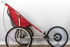
This system is based on two 5:1 spur-geared NEMA 23 stepper motors, driven by TB6600 4A drivers. Each motor drives one of the two main wheels which are quite wide and are not a consistent diameter, due to their fabrication (flexible sheet plastic wrapped around two discs of the same material and welded in some way)
The 8mm dia gearbox shafts have a flat section to allow each one's aluminium wheel to be mounted using 2x M4 socket head bolts. The solid hard black rubber tyres that came with the wheels didn't grip the wheelchair wheel surface very well with the application force we were able to generate so I replaced them. I'll do a project log on this.
The stepper drivers are controlled by an Arduino Nano mounted in a breakout board and the control system definitely deserves a project log to itself.
The power is provided by two 7Ah sealed lead acid batteries in series. There is an in-line blade fuse holder between the batteries, which holds a 10A automotive blade fuse. A domestic plug fuse and holder would also work here if you want to make parts more readily replaceable for the user (although you'd also want to make the fuse holder easier to reach than in this design). There is a separate power switch which is in series with the batteries and has 3 positions:
- Motors and controls connected to the battery,
- Everything off,
- Charging socket connected to the battery.
The charging connector is a 3 pin XLR panel mounted socket that is often used in audio equipment but appears to have been adopted as a standard for charging 24V wheelchair and mobility scooter systems. It is mounted in an enclosure with the power switch that I 3D printed but could easily be substituted with a small ABS enclosure. The power switch and charging socket enclosure is to be mounted on top of the batteries, under the front of the wheelchair seat.
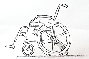
The wheelchair allows you to adjust the main wheels axle back and forward, as the user leans back, onto the caster wheels, to move the wheelchair and leans forward onto a footplate to keep the chair still when bowling, so the balance points can be important to some users. This meant that we couldn't fix the motors to the wheelchair frame and apply suitable pressure between the motor drive wheels and the main wheelchair wheels to reliably transmit driving force.
In response, Andy came up with a brilliant sliding plate that used cot springs to pull the drive wheels onto the main wheelchair wheels, anchored on the shaft/axle of the wheels (which doesn't rotate) using hooks. The spring rate and travel in the cot springs also kept the wheels in contact and under even load despite the variable diameter of the wheelchair wheels. The sliding plate was constrained by pvc pipe brackets around the central tube of the wheelchair frame, so it could only go backwards and forwards. A pair of brackets at the rear stopped the mounting plate from riding up and away from contact with the wheelchair wheels when reversing. The other feature of the sliding plate is the powered engage/disengage system that will get its own project log.


 rsramyasatish3
 Dillon Nichols
Hi everyone, thanks for all the likes and follows, both up to this point and in future. Please accept my apologies for not individually thanking all of you as the HaD.io emails suggest but my feed gets rather filled with project teams thanking individuals. I thought this way would be less annoying for everyone.