 davedarko
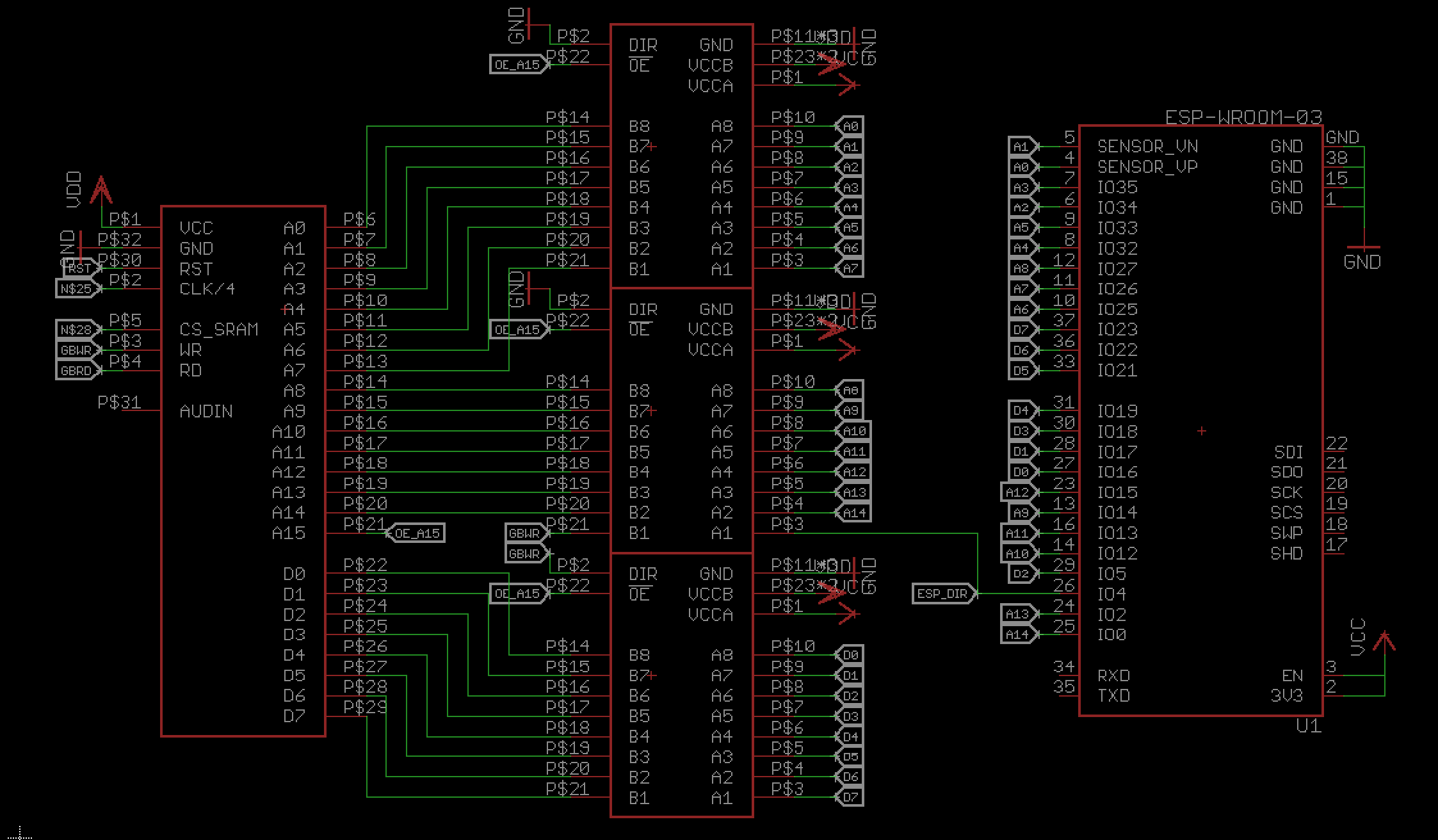
I was able to drop a 74LVC8T245 level converter and connect the address pins. A15 on the Game Boy is basically the "chip select" for the ROM / cartridge, when pulled down, since the address space of the 32kb is 0x0000 to 0x7FFF. SO I use that for the output enable pin on the lvl converter.
The Game Boy write pin will define the direction of the data pins lvl converter. The address lines will be pulled low, meaning the direction is always B->A. I use the pin that was previously the A15 pin to tell the ESP the direction of the communication.
A0-A3 are connected to input only pins of the ESP. Not unlike the ESP12F there are some pins that are connected to the SPI flash on the module and shall not be connected otherwise.
So far I only have the RX and TX pin free, but I consider to have the RST line on a transistor - maybe I need to hold the game boy in a reset state for a while, for the ESP32 to boot up and set all pins.
Not on the picture is the current power supply. I'm a bit worried about the two AAA / LR03 batteries in my Game Boy pocket, they're not that powerful in general and with the LED backlight it's not better. Drawing from the 5V switch mode to convert to up to 250mA will be a challenge. I might need to add a LiPo and/or some tantalum capacitors to make it work.
Discussions
Become a Hackaday.io Member
Create an account to leave a comment. Already have an account? Log In.