 Ramon Imbao
Below, I detail how to properly assemble the watch from bare board to finished product.
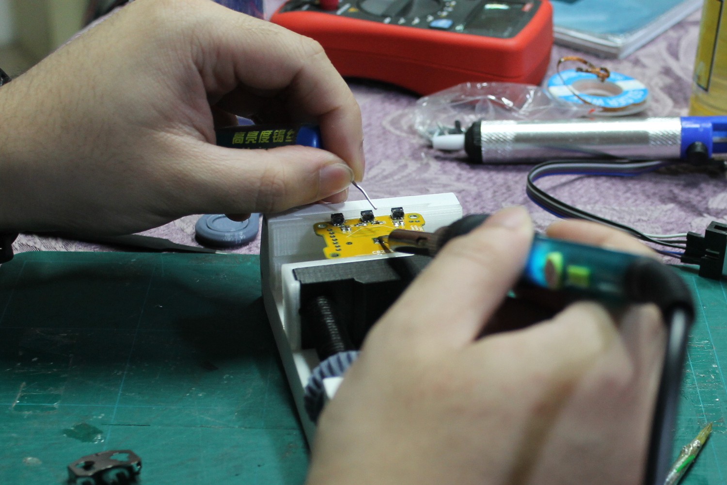
--- Tools used
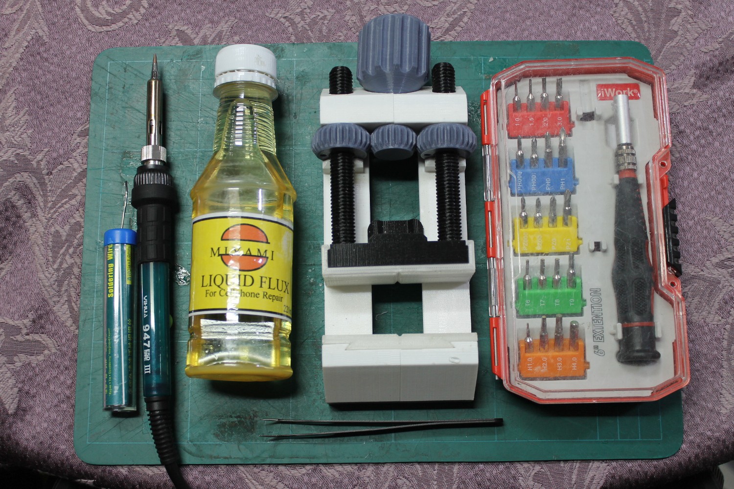
- Soldering iron and lead (Thinner is better)
- Liquid flux (Pictured above is an el cheapo flux)
- SMD tweezers
- PCB vise (I don't own helping hands)
- Screwdriver set
- Solder wick (not pictured)
Have the BOM handy to easily identify which part goes where!
--- Bare board
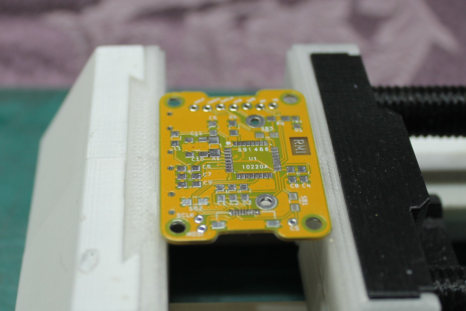
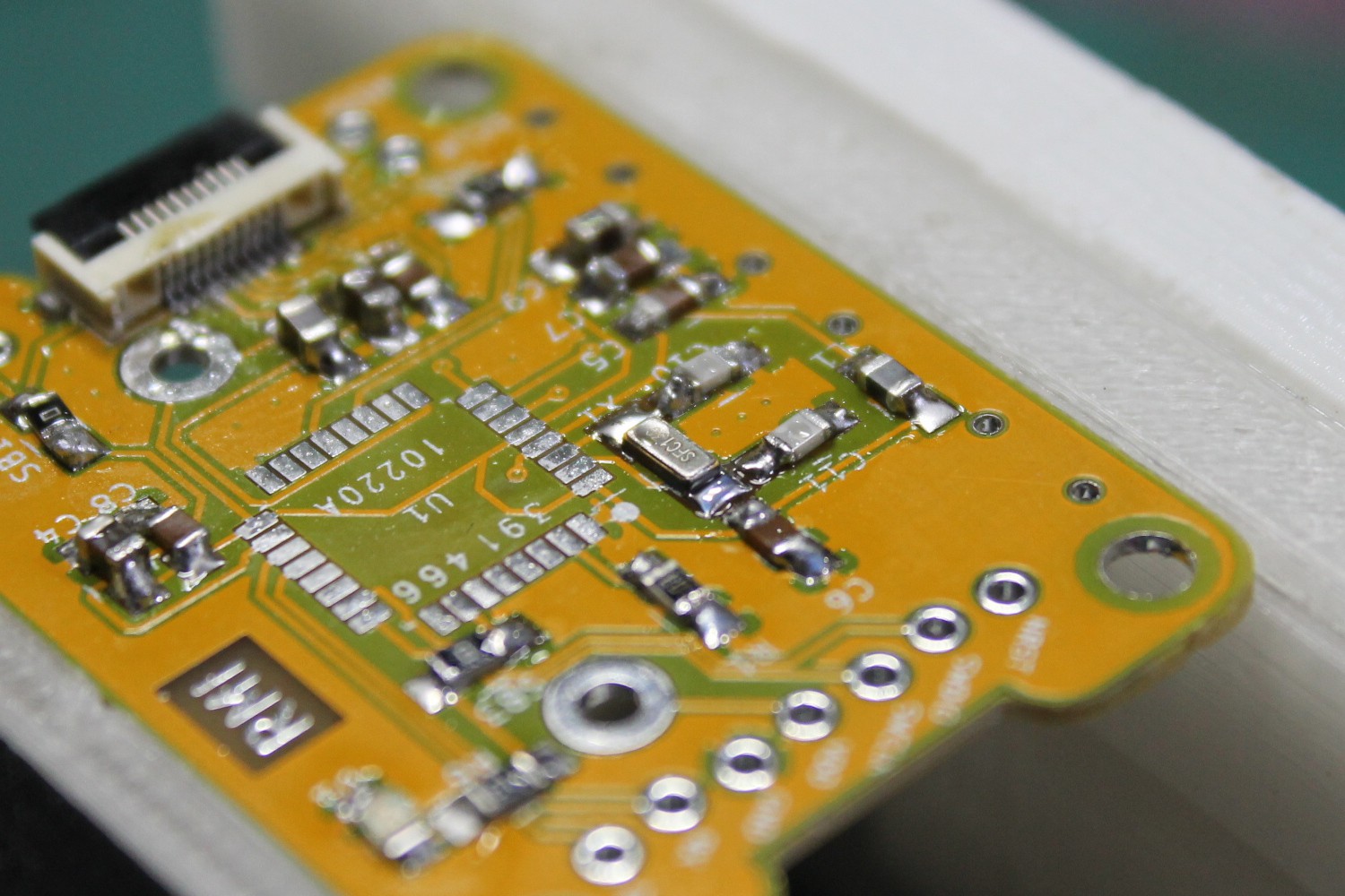
Firstly, we'll work on the top part of the board. Specifically, the first thing I like soldering would be the FPC connector. It's the most difficult one to solder with a 0.5 mm pin pitch.
--- FPC connector
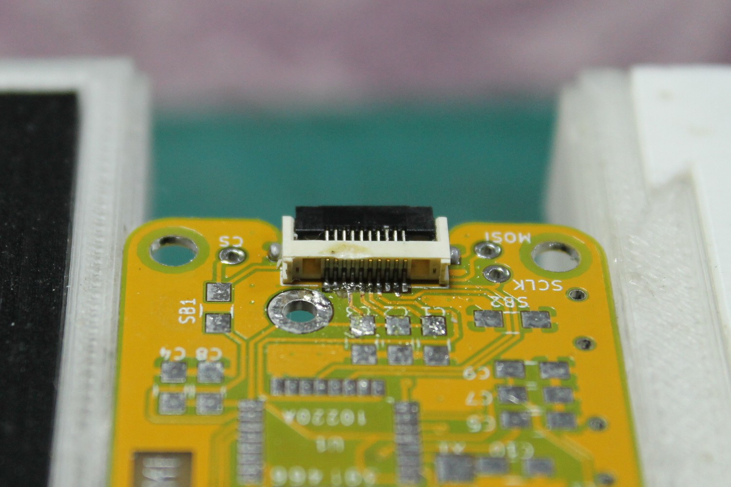 Use plenty of flux and a solder wick to wick away any excess solder. Let's say pin 1 is the leftmost pin. (It's not)
Don't worry about shorting pins 1 and 2, or shorting pins 3, 4, 5, and 6. Those are GND and VBAT respectively. The rest of the pins must be isolated from each other however.
--- Passives
Solder all the passives on the top board. Just go through the BOM, and take your time. Make sure to do a better job than I did as seen in the photo.
--- Crystal
I read somewhere that you shouldn't heat up the crystal too much or you'll damage it, so take care in soldering this.
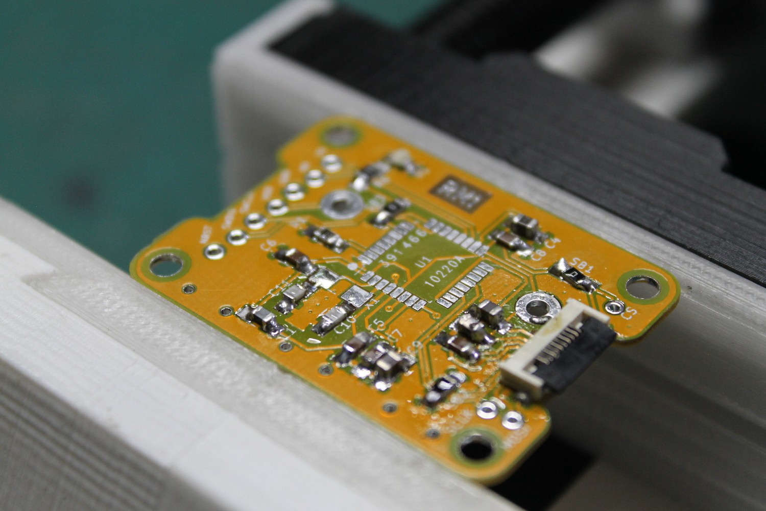
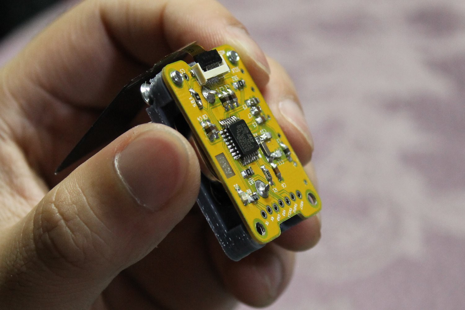
--- STM32 IC
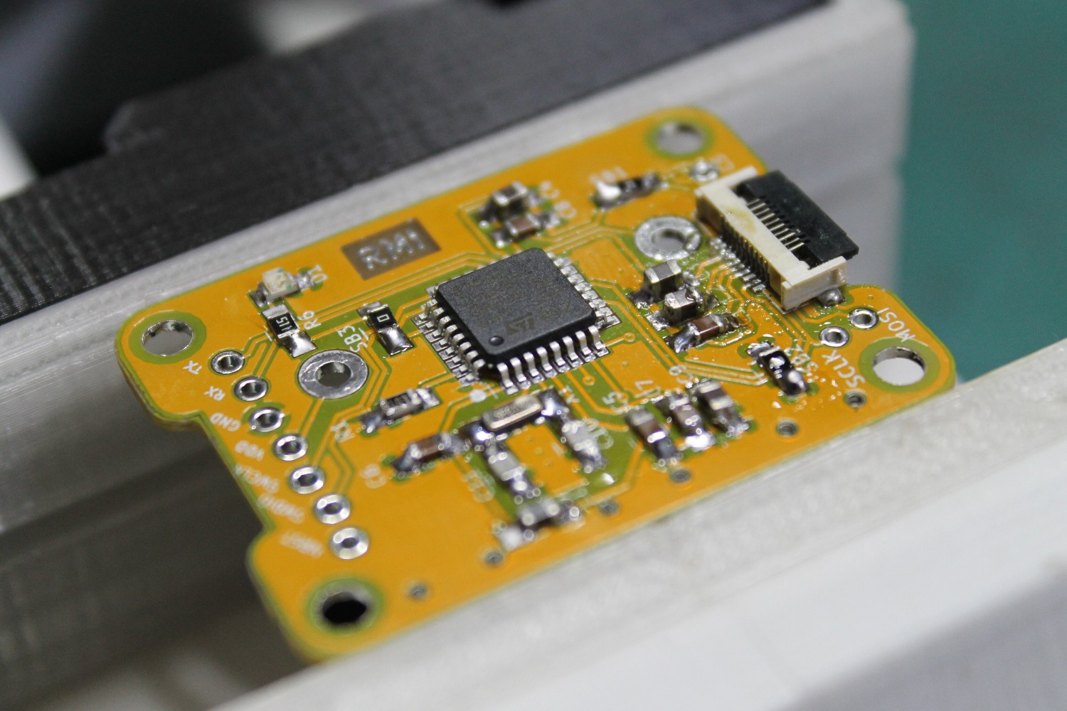
Align the IC on all the pads. Make sure that the dot on the package matches the dot on the board.
Here it is all soldered up. As you can see, I was very liberal with my flux.
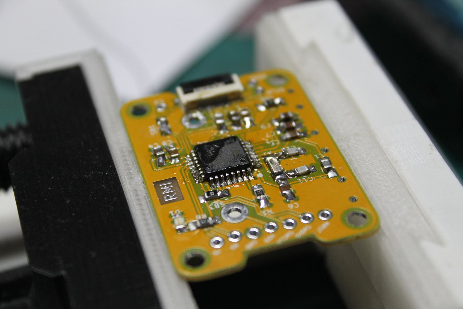
--- Passives (back)
Now you can flip the board around and solder the rest of the passives at the back. All of these are just 100n capacitors and 10k resistors.
--- Buttons
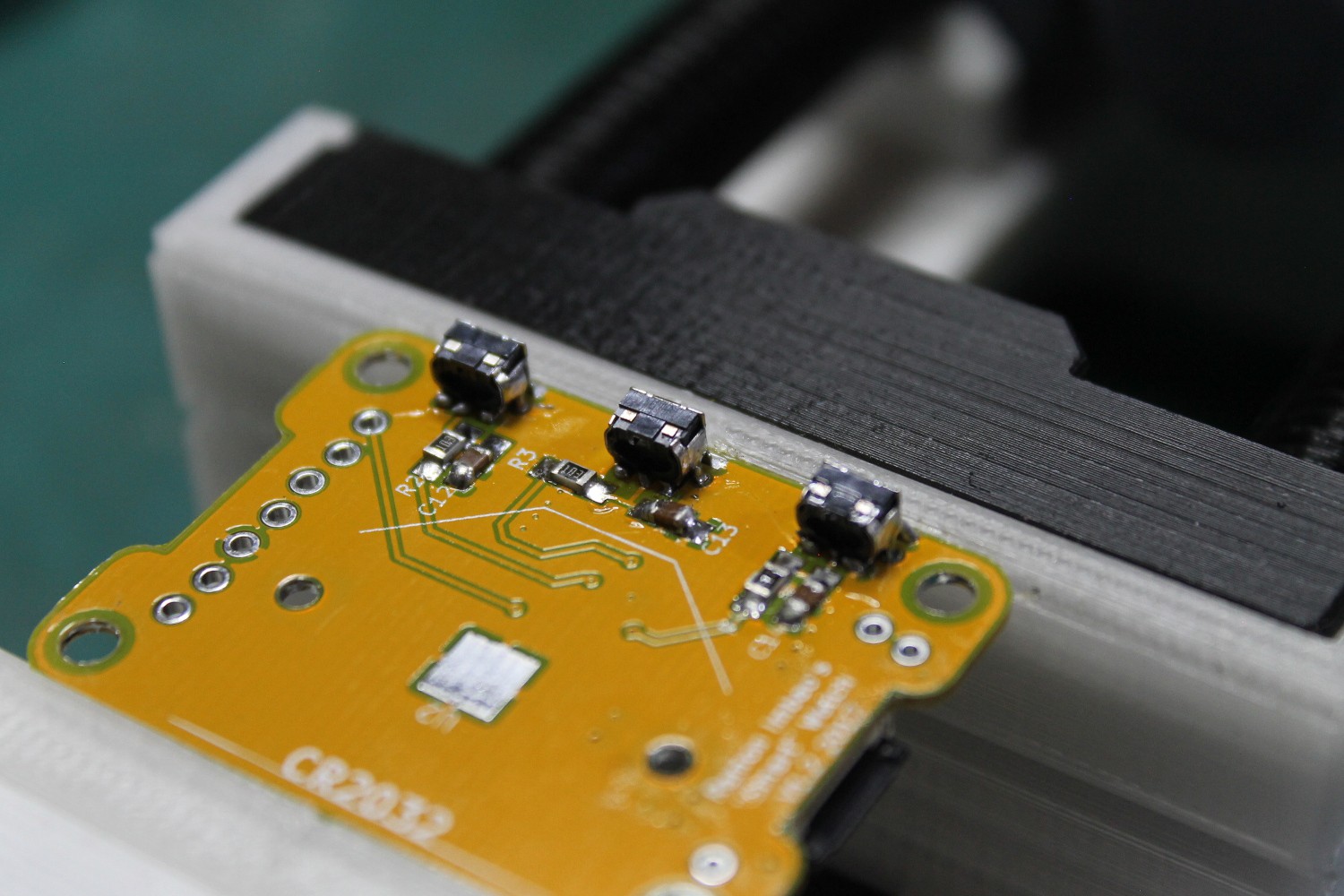
Place the buttons and align them using the holes located on the board. It's a bit more difficult to solder these since the leads don't extend outward. A hot air station might be better suited for this.
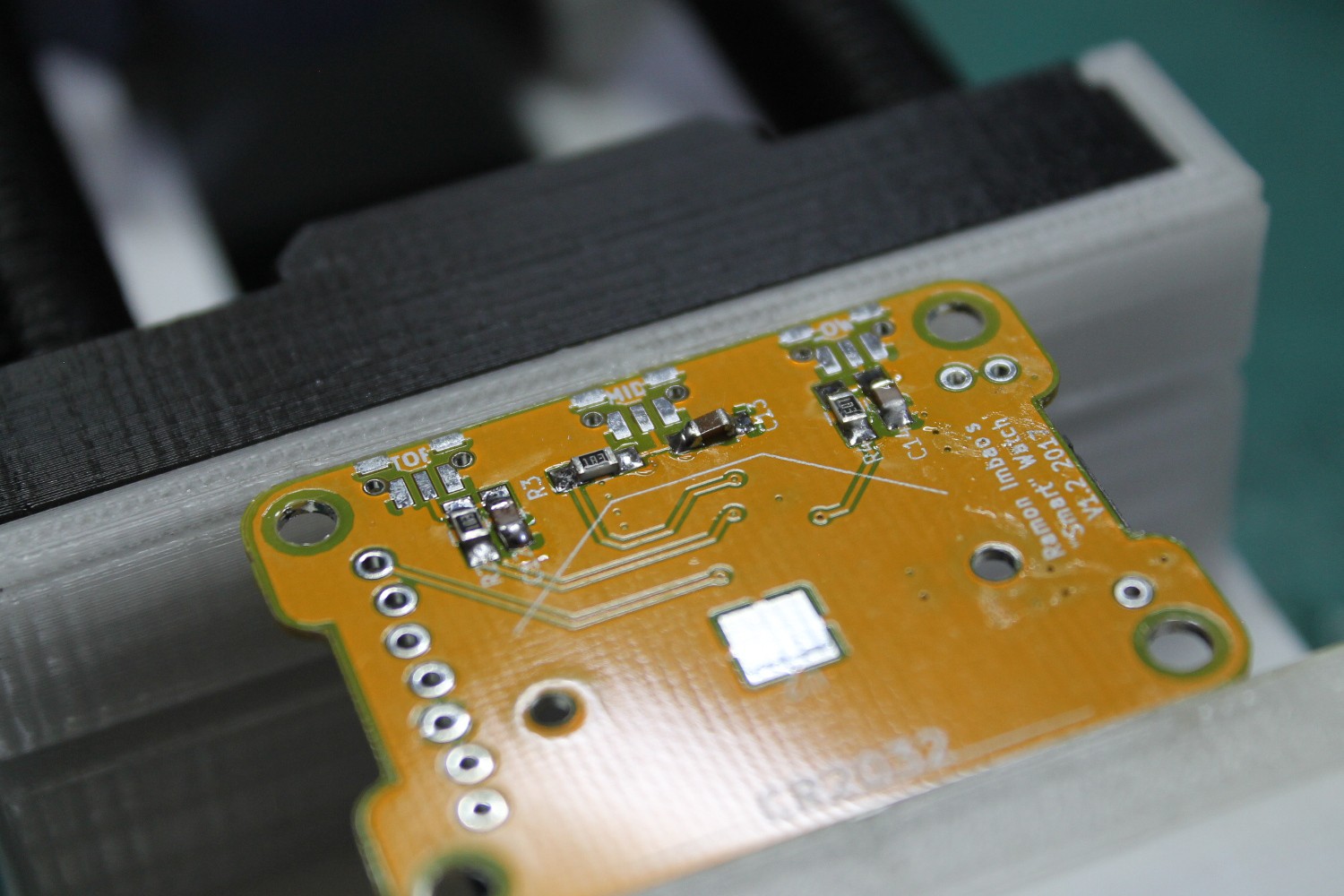
--- Solder pad
Don't forget to add a tiny bit of solder to the big square pad. This helps create a tighter fit on the battery and ensures a good connection. This should create a small bump, like maybe 1 mm thick or less.
--- Battery holder
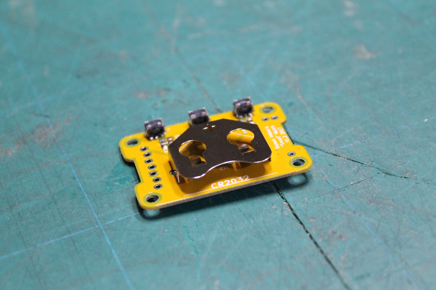
Finally, solder the battery holder on. It's the only through-hole part in the build.
--- Connect STLink
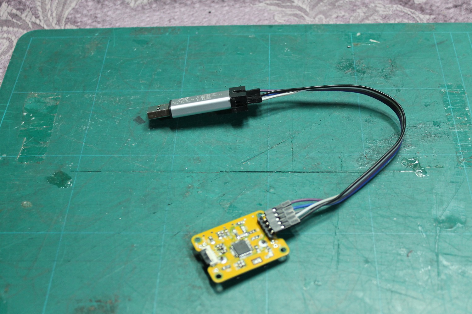
I used a Chinese ST-Link clone. Just connect the five relevant pins from the programmer to the board: SWCLK, SWDIO, NRST, VCC, and GND.
--- OpenOCD
Open up a CLI. Type in the following command to start up the OpenOCD debugger.
(I used Linux for this part. There should be tutorials online about how to set up OpenOCD for Windows. Actually programming the part is OS-agnostic, so just search for that one specific tutorial to get OpenOCD set up)
openocd -f interface/stlink-v2.cfg -f target/stm32l0.cfgThe output should be something like this:Open On-Chip Debugger 0.10.0-dev-00399-g19df456 (2016-11-04-15:40)
Licensed under GNU GPL v2
For bug reports, read
http://openocd.org/doc/doxygen/bugs.html
Info : auto-selecting first available session transport "hla_swd". To override use 'transport select <transport>'.
adapter speed: 300 kHz
adapter_nsrst_delay: 100
Info : The selected transport took over low-level target control. The results might differ compared to plain JTAG/SWD
none separate
Info : Unable to match requested speed 300 kHz, using 240 kHz
Info : Unable to match requested speed 300 kHz, using 240 kHz
Info : clock speed 240 kHz
Info : STLINK v2 JTAG v27 API v2 SWIM v6 VID 0x0483 PID 0x3748
Info : using stlink api v2
Info : Target voltage: 3.216787
Info : stm32l0.cpu: hardware has 4 breakpoints, 2 watchpoints--- Programming with SW4STM32Fire up System Workbench for STM32 (SW4STM32), load the project, and flash it to the board by hitting Run.
--- Connect screen
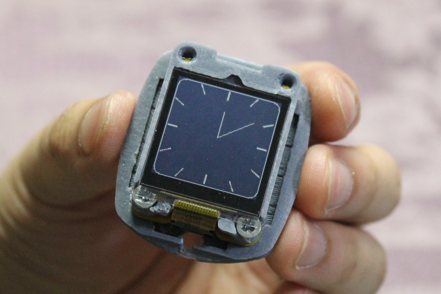
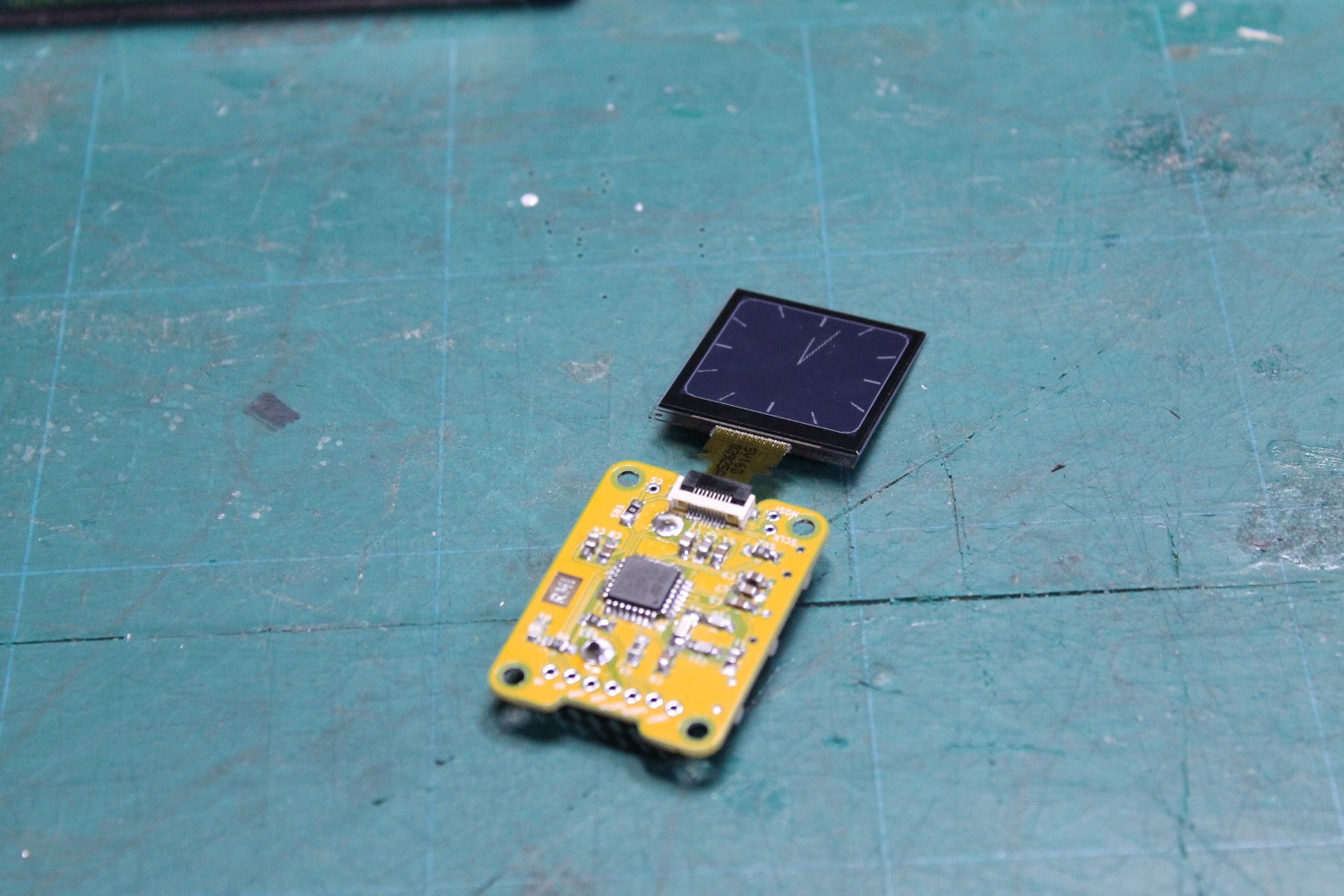 Disconnect the programmer, connect a battery, and connect the screen via the 10-pin FPC connector. You should see the clock face on the display.
--- Test buttons
Press the buttons. The top and bottom buttons should move the minute hand forwards and backwards respectively. The middle button should reset the second hand. The previous picture doesn't have a second hand so this will have to be manually tested. You could also uncomment the lines in the code to enable the second hand.
Anyway, if the buttons don't work, make sure the solder joints are proper. Redo if necessary.
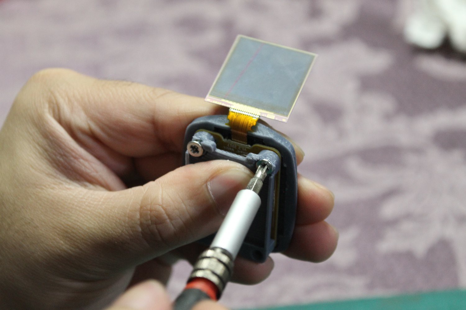
--- Attach screen support
IT IS HIGHLY RECOMMENDED to pre-tap the holes on the screen support. You can use an M3 tap or just use a screw and screw it all the way to create threads.
Place the screen support on the board and partially screw in two M3x8 countersunk screws at the bottom. Take note of the orientation of the part in relation to the screen.
The screws should stick out by that much so you can still place it on the back piece and screw it in.
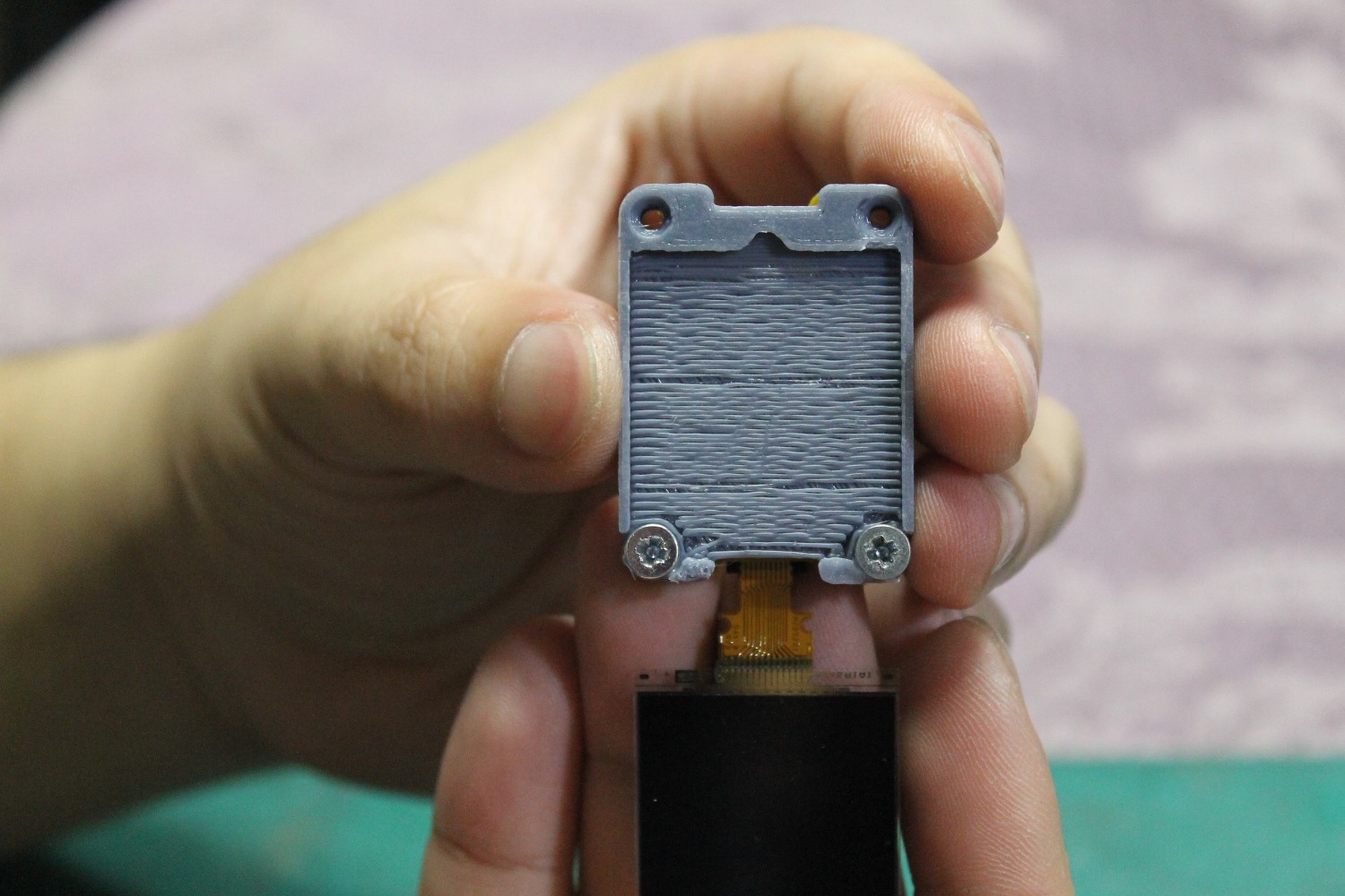
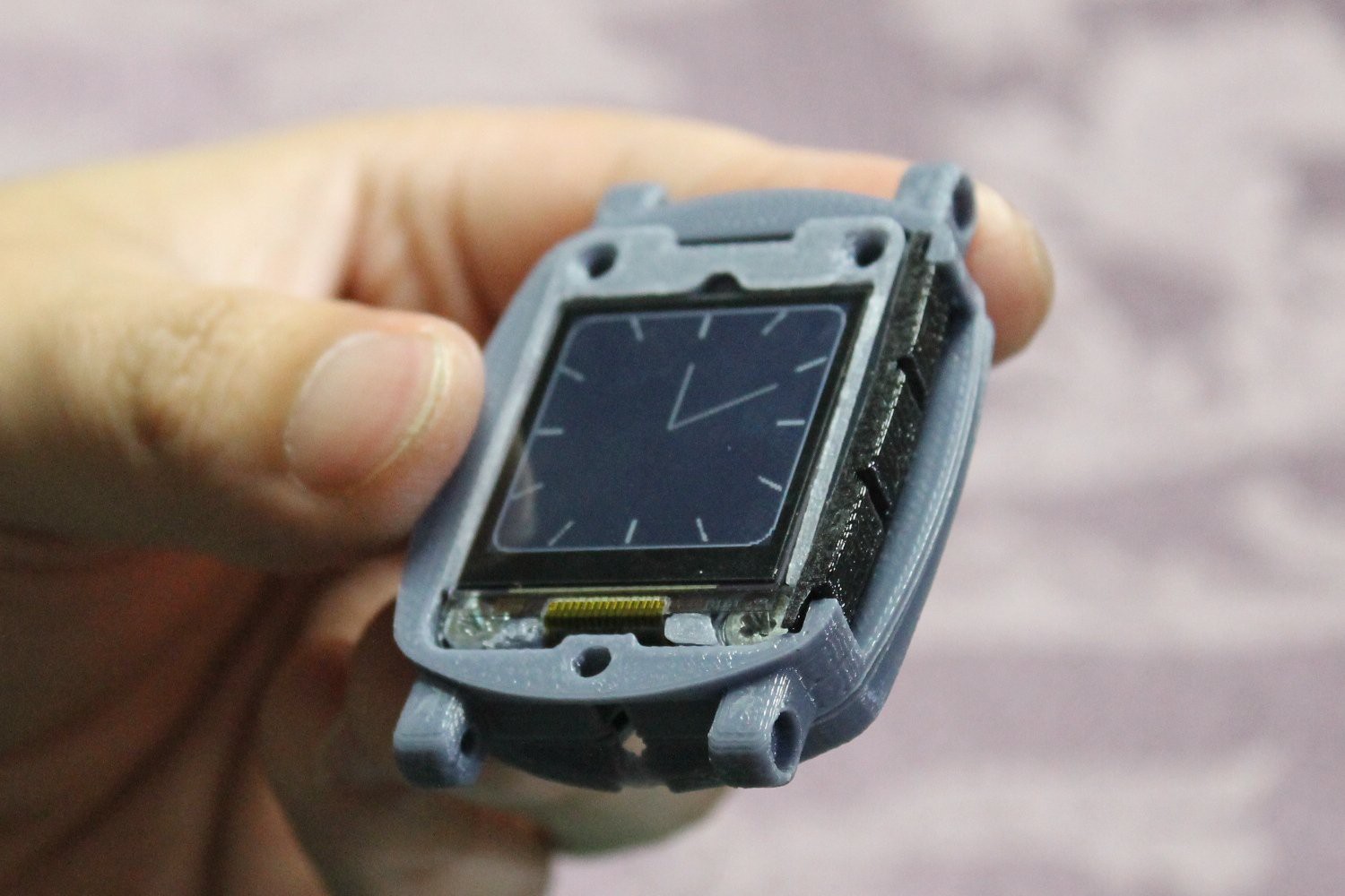
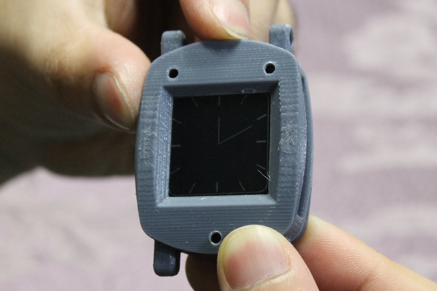
--- Back piece
Here the board and screen support is being screwed into the back piece. There is only a small section where you can thread this in, so be careful you don't enlarge the hole. Tighten the screws until the top of them is flush with the screen support.
The screen should be able to sit flush on the screen support. Be careful not to bend or shatter the LCD when inserting. These things are very fragile!
--- Middle piece and flexible buttons
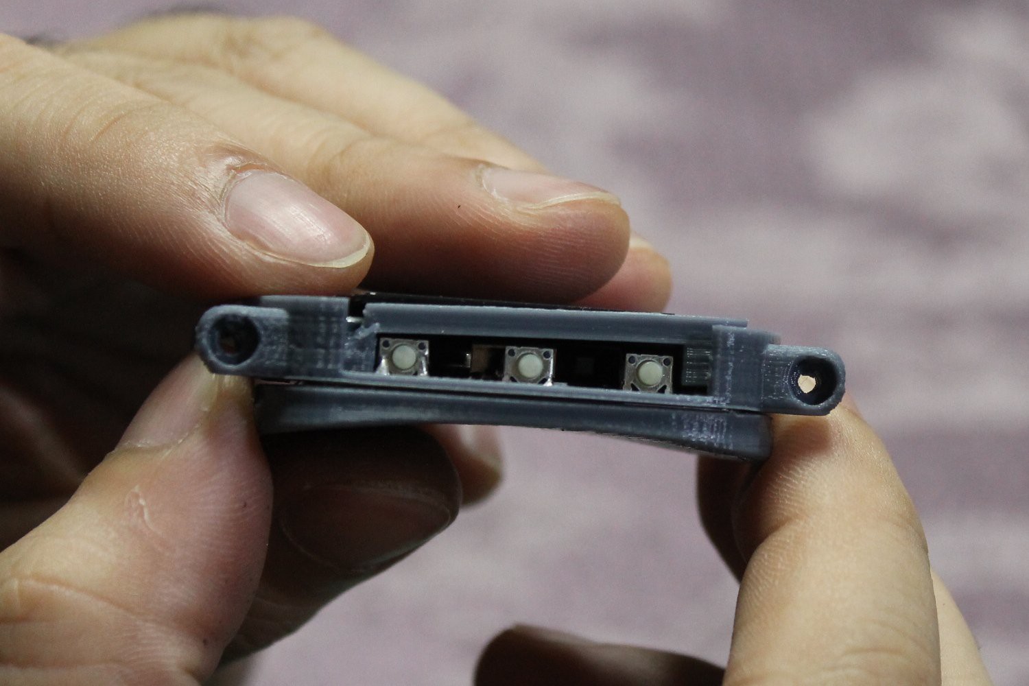
Now you can insert the middle piece through the assembly. Take note that the hole goes on the side where the buttons are, and the thin section is nearer to the bottom.
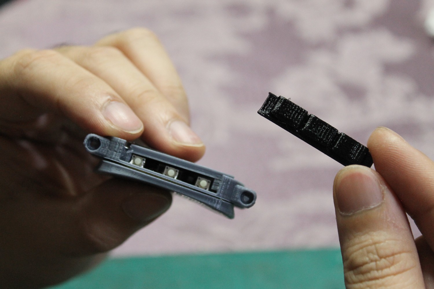
Now place the flexible buttons inside. Note that the actual buttons are offset vertically from the center and are flush at the top.
--- Fit cover and screw from back
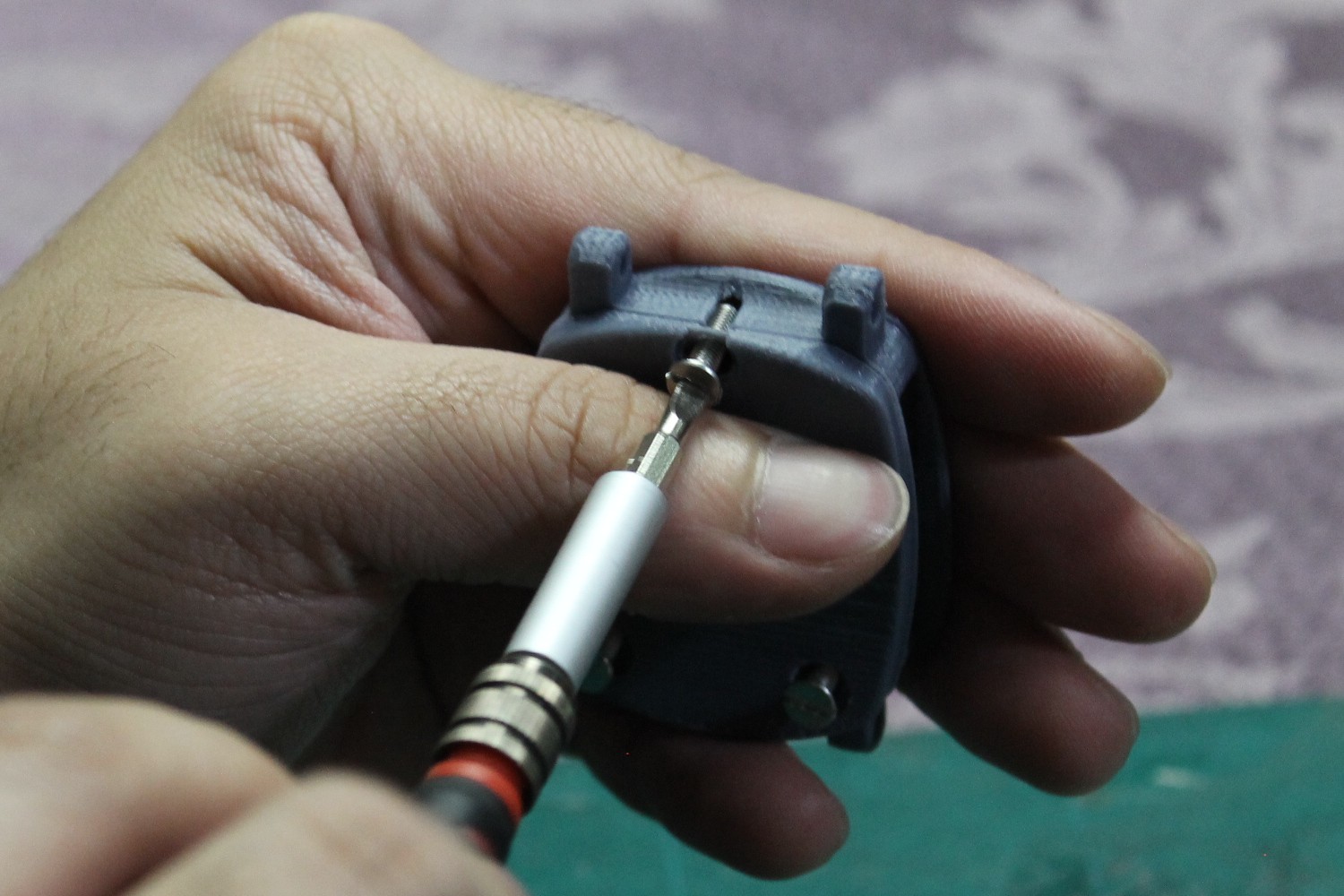
Place the cover in front and insert the M3x12 countersunk screws from the back. This may be super tight if you don't tap the screen support part beforehand.
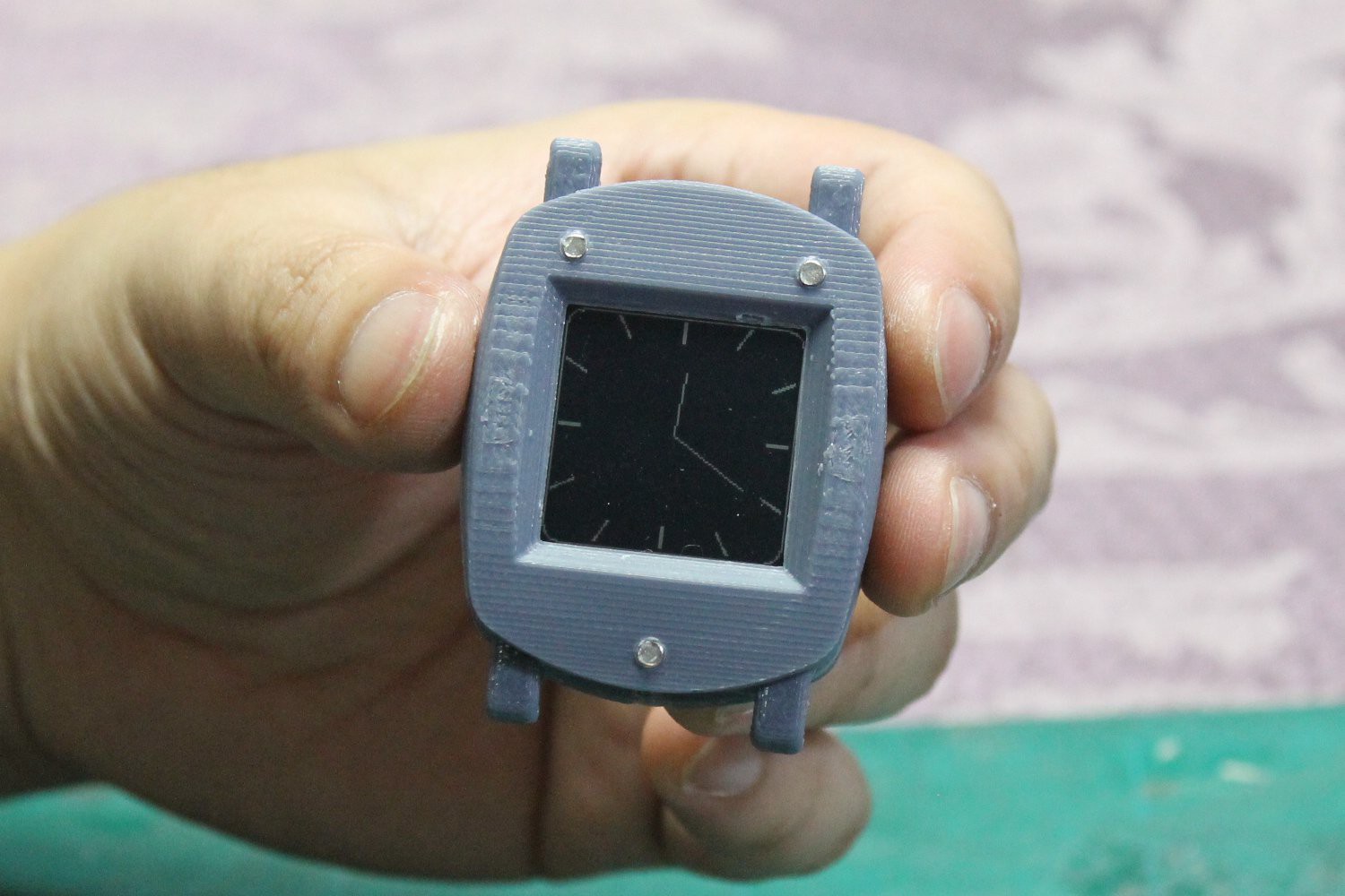
Almost complete. Yes, the screws stick out somewhat, but it's not bothersome.
--- Attach straps
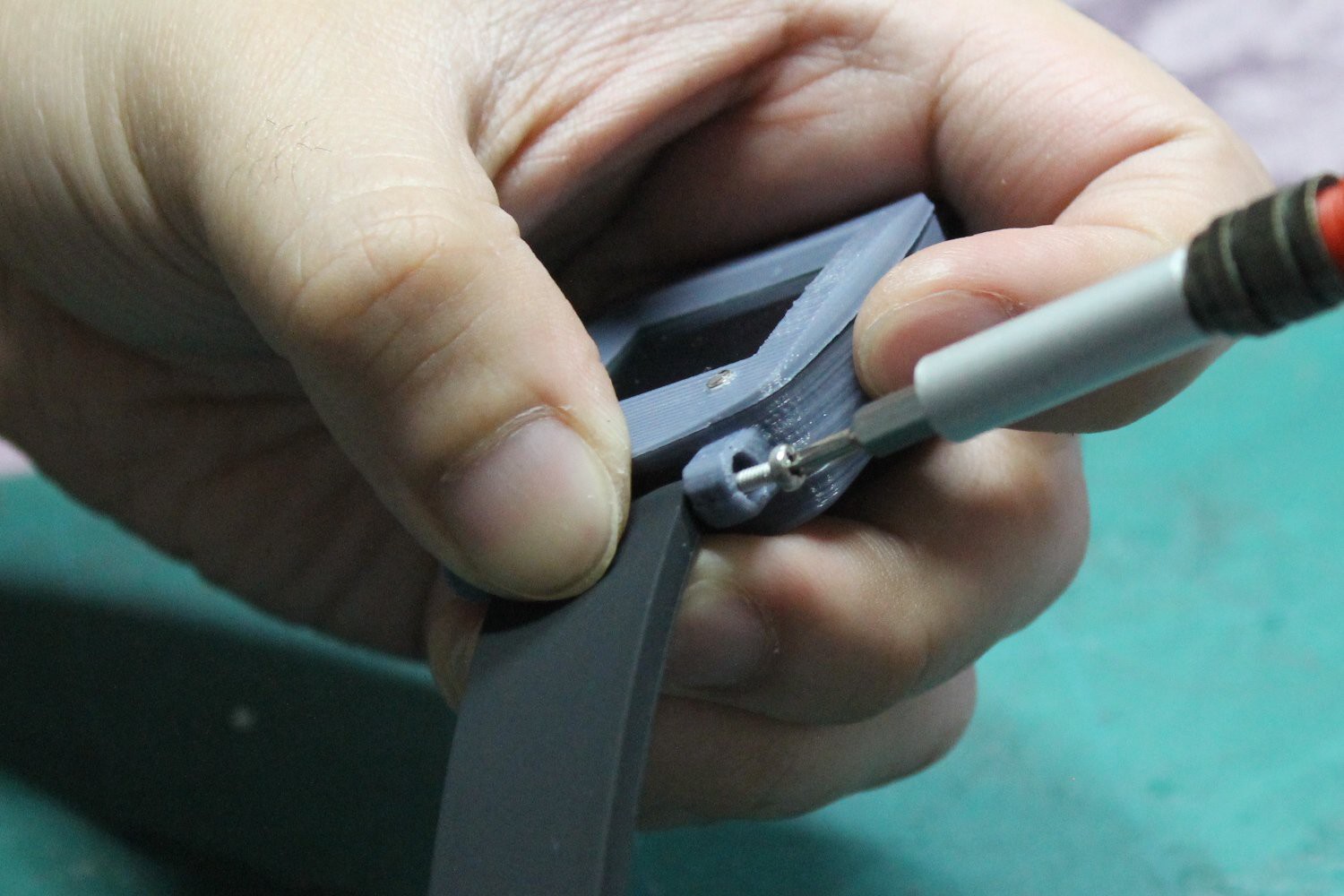
Use the M2x12 cap head screws to attach the straps to the body. There are four in total.
COMPLETE!
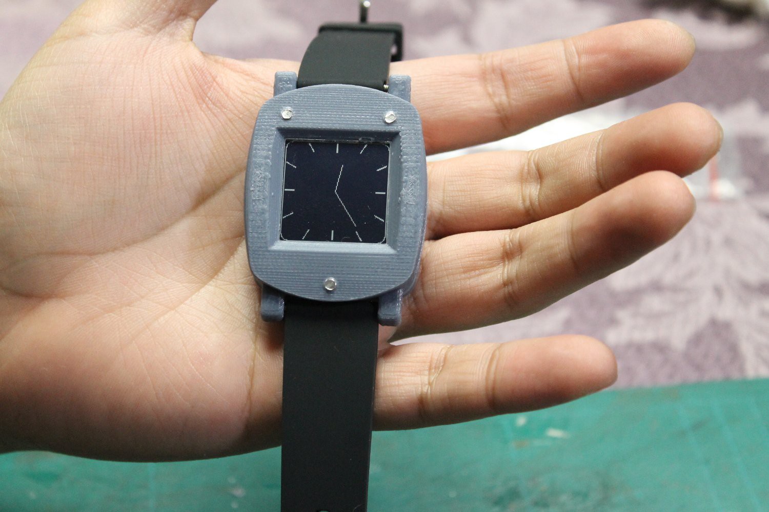
The watch is complete! Wear it with pride. Make more for your family and friends.
Discussions
Become a Hackaday.io Member
Create an account to leave a comment. Already have an account? Log In.