 Marcel van Kervinck
History followed one path
There were many other ways
It will always be like that
Can fewer than 40 old-skool TTL chips implement a multi-megahertz microcomputer with video and sound?
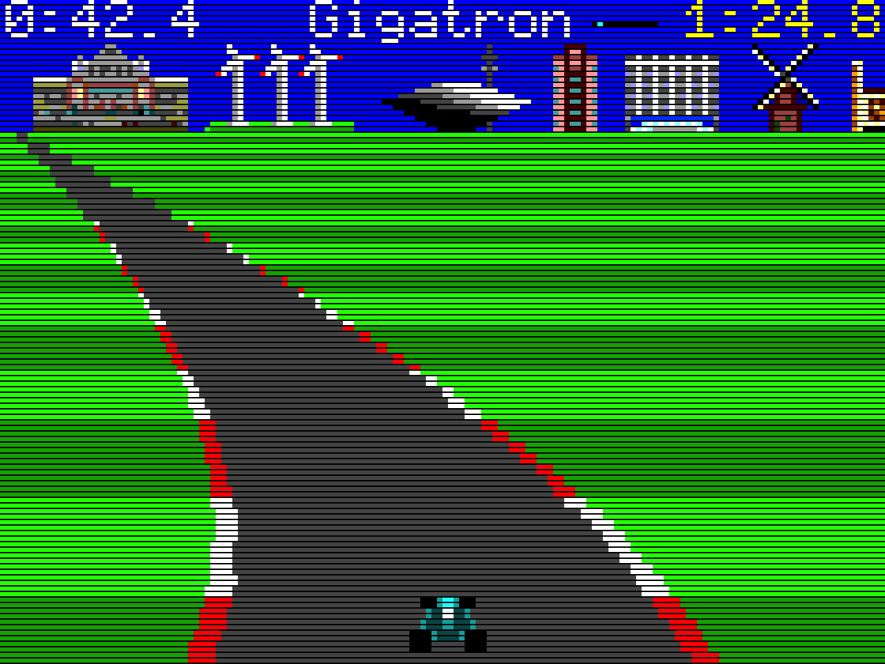
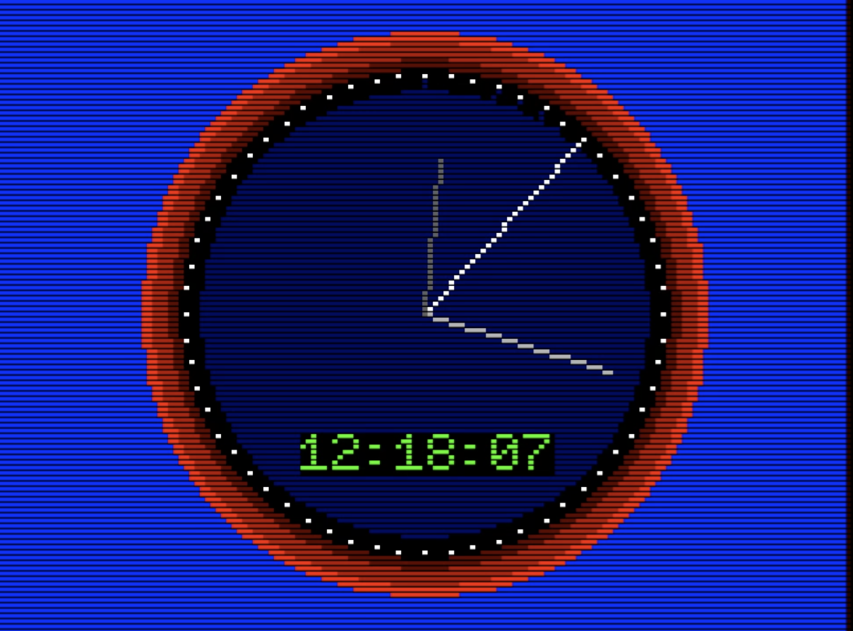
This project started as an exploration of what you can build from 30-40 simple logic chips. It has turned into a general purpose 8-bit microcomputer without any microprocessor driving it. I initially designed this on a large breadboard in early 2017, but soon after that I converted it all to a small PCB. It has VGA-compatible 60 Hz video in 64 colors and can display full-screen images, scroll them and play sound. Soon it will be running games like Pac Man and Space Invaders. But just for fun, I'll keep everything compatible with the breadboard design.
This is what we have now:
• 8-bits system built out of 1970s TTL chips (74LS)
• 34 TTL ICs, or 930 logic gates, for the CPU proper
• No microcontroller and no complex chips (such as the 74181 ALU)
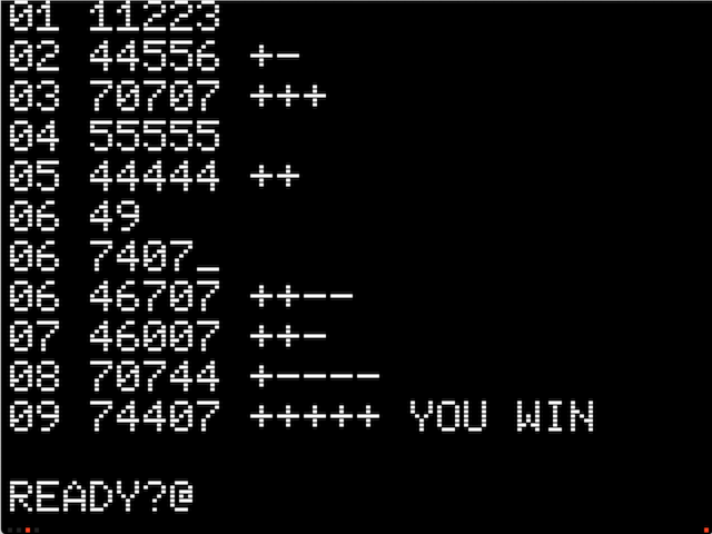
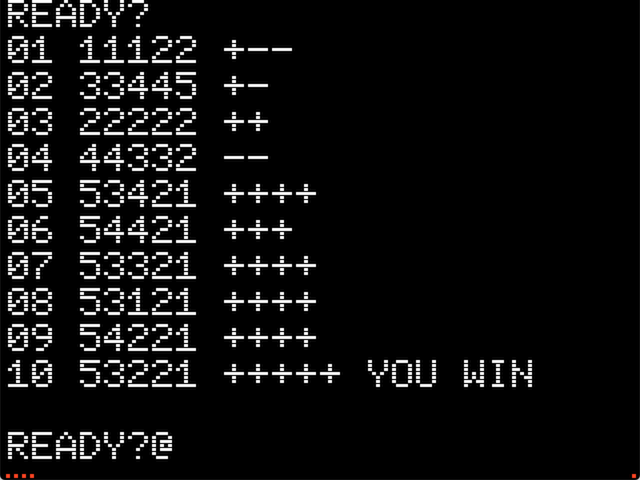
• 16-bit virtual CPU runs ported versions of classic games (Snake, Racer, Tetris, Bricks, ...)
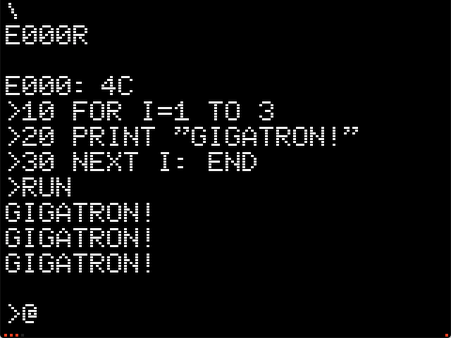
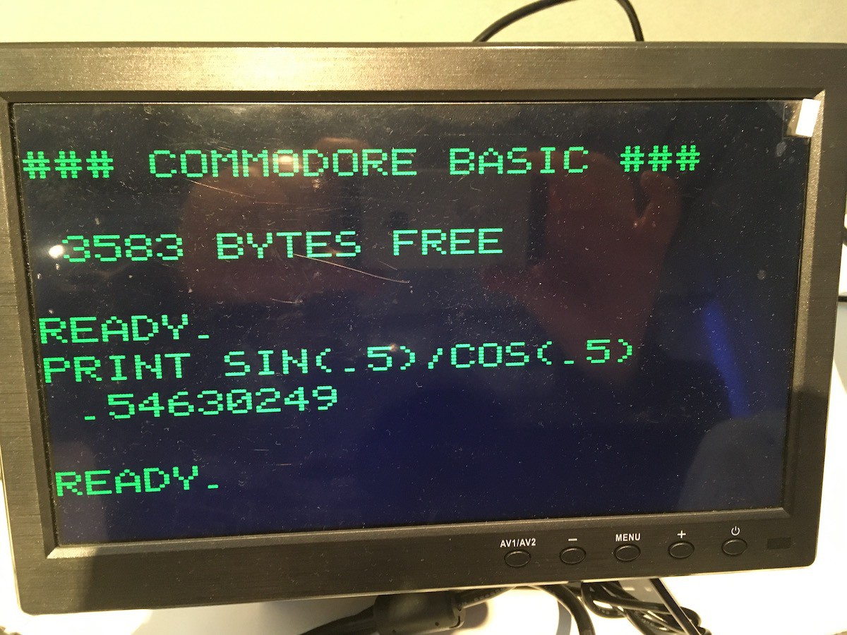
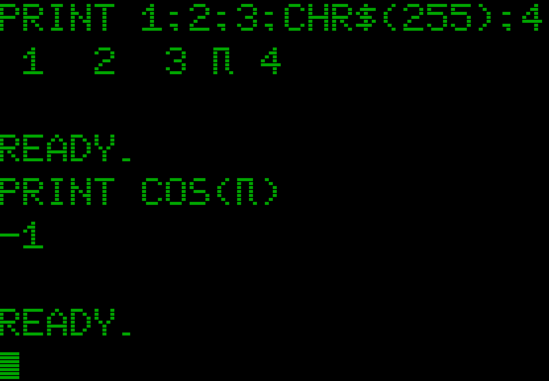
• 8-bit virtual CPU runs 6502 programs such as Microchess and Micro-Soft BASIC without blinking an eye
• Can emulate an Apple-1 including wozmon, Apple-1 BASIC, mini-assembler and some games
• Only simple ICs, such as AND/OR, 4-bit adders, multiplexers, registers and so on
• 6.3 MHz. Can be pushed to 15 MHz with 74F logic and faster RAM
• 32kB 70ns RAM
• Harvard architecture with EPROM for kernel and cold storage. [And no @Benchoff, it doesn't require a large ROM at all.]
• Operates on 2.5W, or below 0.5W for the 74HCT version
• RISC with pipelining: 1 instructions per clock (sometimes 2...)
• Instruction decoding with diodes
• Nice clean instruction set: add, sub, and, or, xor, conditional jumps, many useful addressing modes
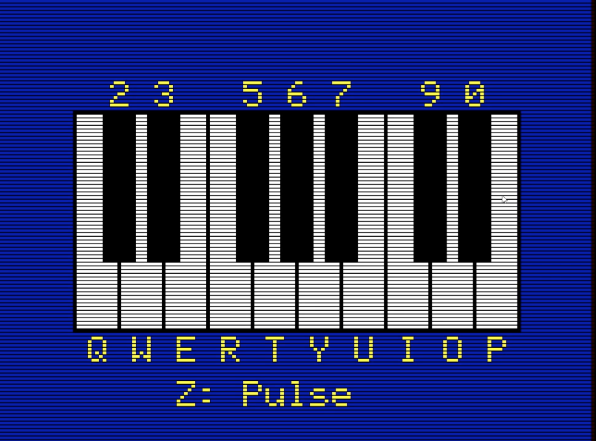
• 60Hz 64 color VGA and 4 sound channels bit-banged from software
• Originally designed and built on a solderless breadboard in 6 weeks (see the logs!)
The build has become a contradiction of itself. To reduce the parts count, every hardware function is essentially software-defined: video, audio and I/O are all handled by software. Video at the pixel level. Audio at the sample level, in 4 channels. Even the applications themselves are running in a non-existent 16-bit processor (aka interpreter).
Yet there is no microprocessor chip in there that runs the software of any of those virtual subsystems: it's all handled by the TTL circuit, acting as a minimalistic CPU and switching rapidly between these tasks. Not only does it work, the board is smaller and faster than the microcomputers of the day, including the first IBM PC. Having no microprocessor might have been better than having any of the time :-)
Check the videos for the current capabilities. The HaD blog section has the full story in all detail, so don't miss that if you're interested.
Some concepts to ponder about before starting
- How many bits? 4, 8, 16, 32, ...
- Software-generated video or hardwired?
- Harvard or Von Neumann architecture?
- Single cycle or multi cycle? Pipelining?
- ALU chips or not?
- Sliced ALU or full width?
A rule of thumb is that a minimalistic four bit system can be done in 10 chips, an eight bitter needs no more than 20 chips and going to 16 bits roughly doubles that again. Not all units double in chip count, but by extending the buses you will also have need for more addressing modes for it all to make sense. For example, a four bitter might work fine with a 256 word memory and absolute addressing, but with larger memories you'll need ways to construct addresses dynamically. Also, add more chips if extra functionality is required, such as high speed, a stack pointer, interrupts, a custom ALU or video.
Simplest possible concept
One concept, probably the simplest, is to replace the TrinketPro from the earlier breadboard VGA from TTL and SRAM with a minimalistic 4-bit TTL CPU. We will then get a working system with around 25 chips, or about 30 if we make a custom ALU....
Read more »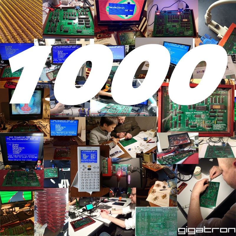 We have decided to stop selling kits once our stock has been sold, which should be in a few months. For us, the Gigatron was always about inventing new things, understanding technology, designing, fine tuning, tinkering, and also about meeting like minded people (and having fun in the process). Making it into a kit had its own charmes, writing a manual, sourcing components, designing a PCB. Packaging and sending out kits, however, resembles a plain job too much, but was needed to create a community of people that would also want to design, understand and tinker.
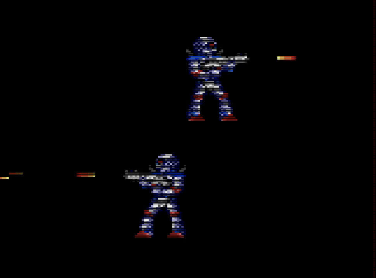


 Matt Stock
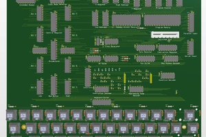
 Mars
Mars
 Anders Nielsen
Rest in peace Marcel.