 Marcel van Kervinck
I'm still uneasy about the planned ALU layout and its control logic. The way to extract "write" and "jump" signals remains clumsy and the STIX instruction doesn't really fit in well yet. It will work, but that one remains a wart. Besides, the alternative ALU, the 10 chip MUX-based design, remains much more attractive.
So I revisited it and realised that of the 8 control lines only 5 matter. That's good news. If that can be reduced to 4 or 3 bits we're done. 4 is easy, but then we still don't have "jump" and "write" signals.
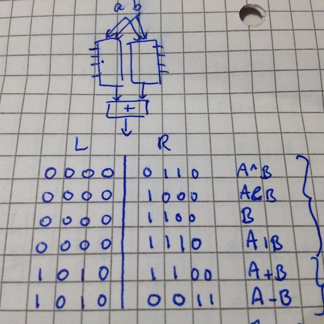
Staring at the dense part of the truth table I realised this is a ROM's job. That can decode 3 instruction bits into to 6 ALU combinations (ADD, SUB, AND, OR, XOR and "B" aka "LOAD"). Doing this in a little ROM we immediately get the "write" and "jump" for free by assigning these to the unused ALU codes. Plus, we'll have a full bit to spare in the instruction word. That might be useful for STIX. Also, managing the two clock phases can become simpler. All combined this has the potential to save up to 3 chips and that is worth exploring.
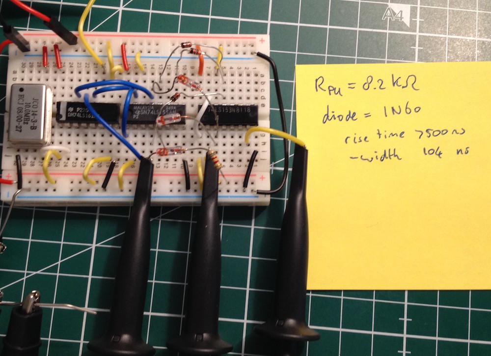
But ROM is slow. So an old idea popped up: maybe, just maybe, we can do the ALU control with a 3-to-8 decoder and a tiny, 6 word by 5 bit, diode ROM matrix? People have controlled Atari's with such contraptions and this will be much smaller. Just 20 or so small diodes. So today I got some 1N60 and 1N4148 signal diodes and started playing. I did some quick multimeter tests first: at 10 mA the 1N4148 drops 400 mV and the 1N60 is about ten times better. But both should be ok because TTL allows for a 0.4V drop. Are they also fast enough? Lets measure:
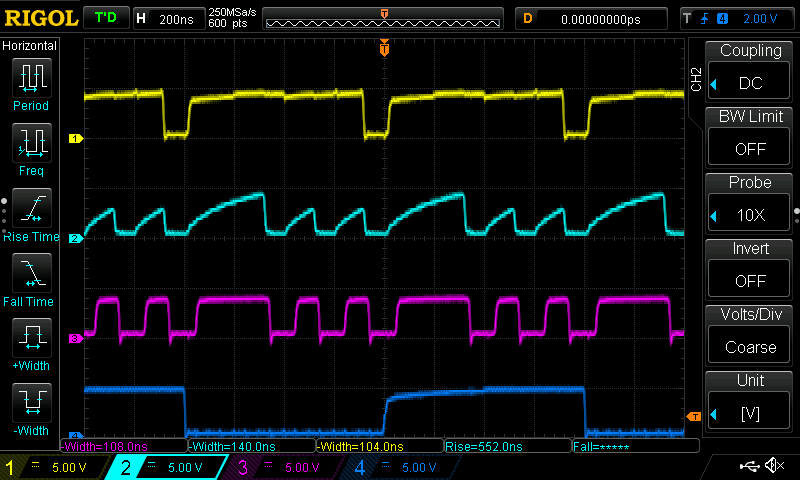
Ignore the yellow and blue. The cyan signal is the diode stage output. This signal looks poor: it has very slow rises. But once above 2V TTL has a "H", and that happens fast enough. We see the next stage (purple) rectifying it nicely. For the ALU this will be more than good enough: both diode types seem to give proper signal transfer through the ROM matrix.
So are we good? Not yet... In reality this ALU will have 8 parallel MUX chips and each one has 8 inputs. Ultimately they are all connected to the same word line coming out of the decoder.
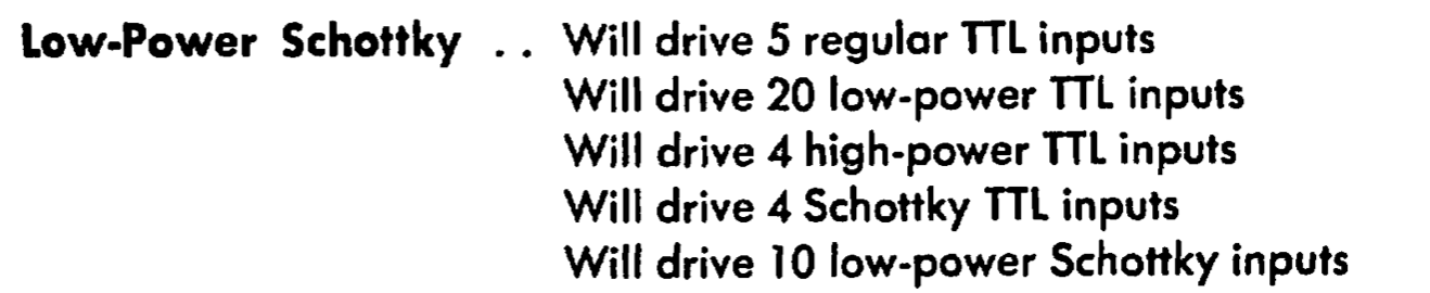
That still doesn't sound good at all! We have an effective fanout of 8*6, + 1 for the carry. 49 is definitely more than 10. Worse, we have some nasty voltage dropping diodes in the path. Maybe this idea was too good to be true and this is a dead end. To be continued...
[ Postscript: An obvious solution to the fan-out issue is to feed the diode ROM into an inverter row. It is not really the decoder's problem anyway, as the root cause lies with the MUX-based ALU concept. We'll need 6 inverters, not 5, because one of the signals goes to 2 pins of every MUX (there are eight of them). A simple 74LS04 hex inverter IC will do the trick. An added benefit is that the ROM logic now flips from negative to positive. We can really see every operation's truth table right in front of us! And save on a few diodes along the way... ]
Discussions
Become a Hackaday.io Member
Create an account to leave a comment. Already have an account? Log In.