 Marcel van Kervinck
The control unit (CU) uses decoder IC's and diodes for decoding the operation and addressing modes. I'm toying with plain 1N4148 (silicon), 1N60 and BAT85 (both Schottky) diodes. Surprisingly, all seem to work pretty well. Here they are all mixed more or less randomly on the breadboard.

The diodes between INS (74LS155) and INV (74LS240) form the operation decoding ROM matrix. The diodes connected to MODE (75LS138) pull the control lines for register loads and RAM address generation. The diode mess looks fragile, but in reality it all stays in place rather well.
When combining diodes with TTL, there is only 400mV voltage drop to play with before entering undefined territory. Some of the diode logic outputs travel all the way across the circuit, which means that supply voltage and ground differences must be controlled over that distance. Also, 74LS requires 4.75V as absolute minimum, or no more than 5% drop.
When I installed the supervisory MCP100 some weeks ago, I already noticed that I had to connect the 5V supply on the same segment in order to boot. If I connected it further away, it simply wouldn't release the reset. This means there is too much resistance between the segments, more than the equivalent of 250mV. A couple of extra bridges solves that. But to troubleshoot this, I found a useful second use for the MCP:
First recall that the MCP keeps the reset line low for as long as the supply voltage is not stable above 4.75V. (Well, the MCP100-475DI/TO does that. In ordering these, every letter means something important). In my circuit it sits next to the reset button, as you can see here:
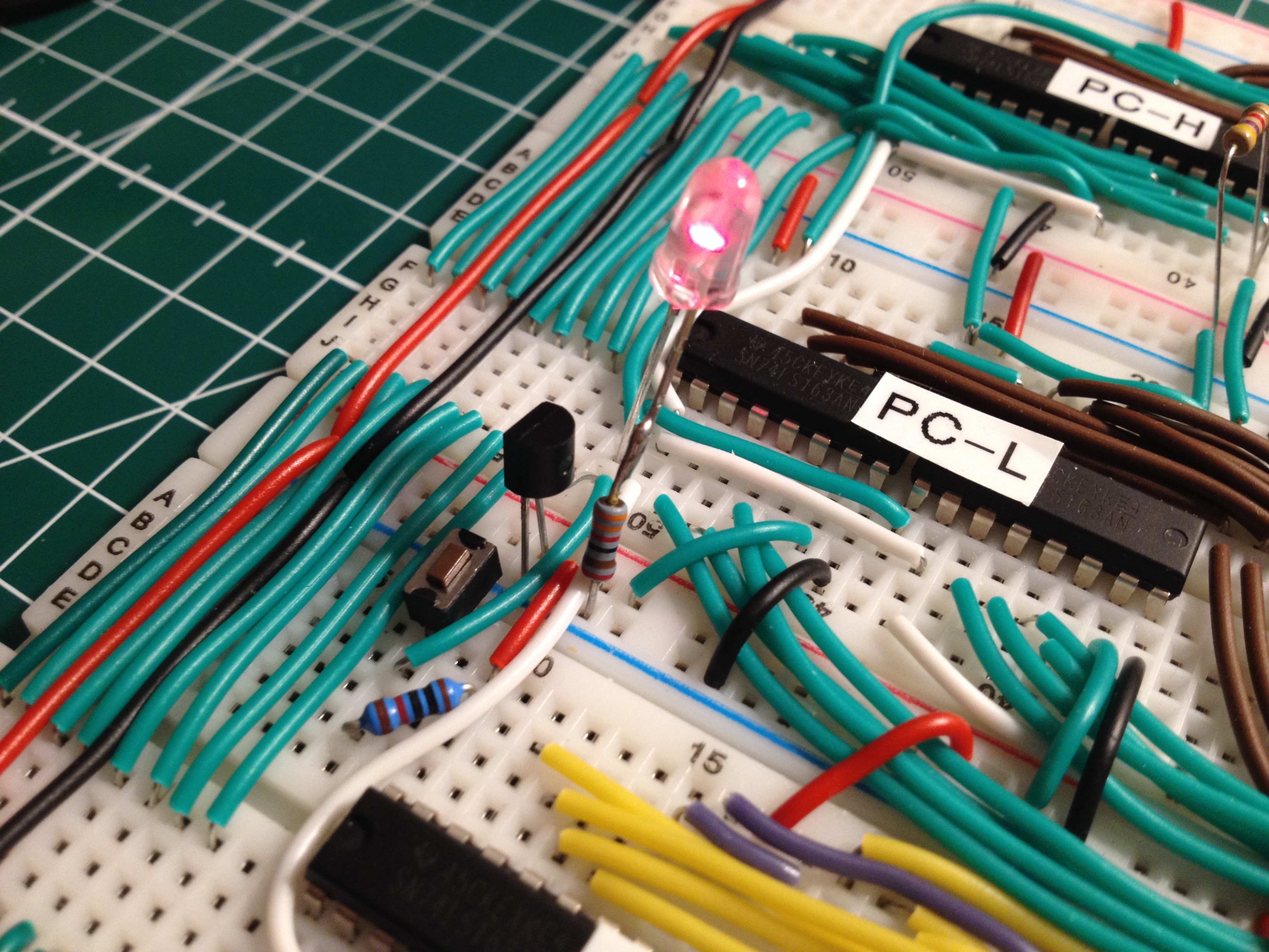
You can spot the reset switch with its 10kΩ pull-up resistor. It controls pin 1, or /CLR, of the PC counter IC's (all four of them). The red LED is just lurking on the reset line as an indicator. The MCP is the three-legged black component that looks like a transistor. It has one leg on the reset line. The other two legs are on Vcc and GND. It is a clever and useful little device. Now it turns out you can make a super easy voltage tester from an MCP, an LED and a current limiting resistor (330Ω), as follows:
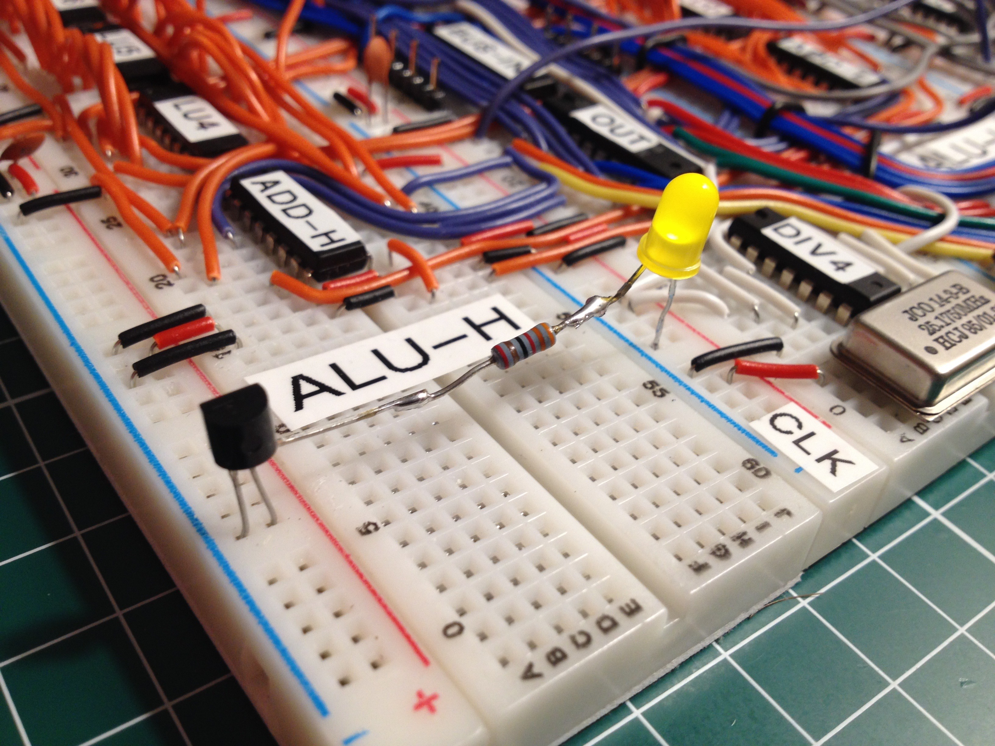
The "reset" leg is now connected to the LED and not to the circuit. If the LED is on, the voltage difference on the supply rails is stable above 4.75V. With this device it is easy to test the voltages everywhere, much easier than with a multimeter or scope. I call this the "canary" because of the yellow light, and because when the light goes out, it signals that that part of the circuit is in danger.
With all voltages controlled, the video image is now stable. I'm still emitting uninitialised SRAM data, but to verify that I'm streaming from the right addresses, I let the CPU draw some lines across the screen, vertically and diagonally. All addressing modes and registers are now exercised, so this is a pretty good system test.

Discussions
Become a Hackaday.io Member
Create an account to leave a comment. Already have an account? Log In.