 Yann Guidon / YGDES
What a day ! Where do I begin ?
Ah yes, yesterday, I was thinking about the I/O system.
With a budget around 500 relays, that translates to 50/18=27 relays per slice (I exaggerate because I/Os are not parity protected but "bear with me". That would be about 16 relays for outputs and 8 for input. BTW, what are these ?
- Input is simple : this is just an external signal that enters the datapath. One MUX per input channel is enough.
- Outputs are a bit more tricky : they need to be latched, so this uses two relays : one for selection and the other for storage.
Now, let's think about this:
- 8 read and 8 writes is ... very similar to the existing register set !
- It appears that 8×16bits of inputs AND outputs is quite a lot (128 inputs wires, 128 output wires...) and I don't think I can use all of them.
So today I merged the I/Os and the register set. This computer uses both "register-mapped memory" AND "register-mapped I/O"...
So far, we already have these 8 registers :
- A1
- D1
- A2
- D2
- R1
- R2
- R3
- R4
Fine, now let's add our four I/O registers:
- I1 / O1
- I2 / O2
- I3 / O3
- I4 / O4
(that's 64 input wires and 64 output wires, not bad...)
Reading I1 will read the corresponding pin while writing O1 at the same address will set the corresponding pin. They are only related by having the same address.
Now, what if you connected, say, I1 to O1 ? Well, you get a register (that can be seen by the exterior) and which can only be read by one MUX8.
And since we don't need as many GPIO, let's now introduce the "extended registers" ! Welcome to
- T1
- T2
- T3
The last one is, well.... hmmm I had to think hard about it but I have chosen to dedicate it to PC.
We have 16 registers, now, guys ! But one half can only be seen by the 2nd read port. The instructions contain these fields :
- SRC : 3 bits
- SRCX : 4 bits (SRC eXtended)
- DEST : 4 bits
SRC is missing some of the action but has its own fun : it gets the shifting done, and gets a bit of immediate values. Each slice can do :
- Pass (direct value from the register)
- Shiflt Left (1 bit)
- Shift Right (1 bit)
- Immediate (short)
(that's a MUX4)
The short immediate value comes from the SRC field, but 3 bits (range from -4 to +3) is a very short range. But there is more :-)
Usually, the complete set of operations is : ROR, ROL, SHL, SHR, SAR, and let's not forget the Carry : RCR, RCL, SHRC, SHLC, and the arithmetic SAR...
They only affect the "edges" of the shifter, so we have to select the value of the next bit that gets shifted in.
- 0 (for SHx)
- sign bit (for SAR)
- Carry (for SxC)
- the bit from the opposite bitplane (for ROx)
That's just a few relays on the edges of the backplane, that use 2 control bits.
We now have a more complete set of single-bit shift operations and 2 more bits to use with the short immediate, no dead code :-) The Pass function can also gain more features, I'll decide later.
(byte swap ?)
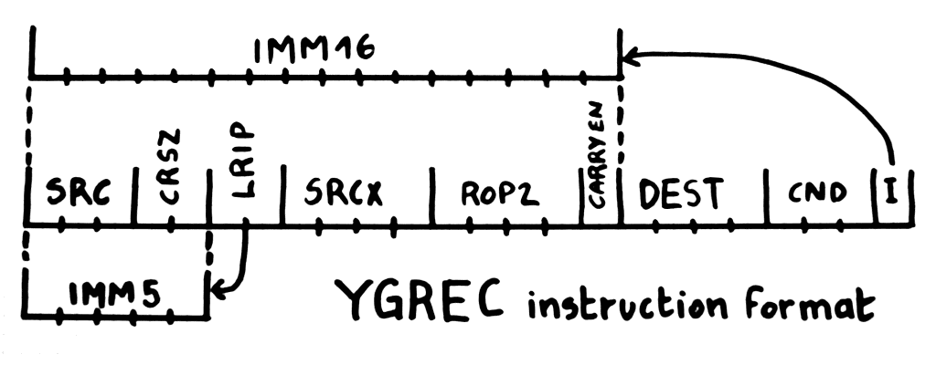
5 bits of signed immediate value is very short, and useful for short jumps for example, but the user needs to load whole 16-bits registers. There is not much room and I'd like to share features with the other instructions so I have decided :
- Common prefix : DEST (4 bits), Immediate flag (1) and CND (condition, a 3-bits predicate) [total: 8 bits, niiiice]
- The remaining 16 bits are either the immediate value or the source and ALU bits.
The source fields are :
- 0..2 : SRC (access the 8 lower registers)
- 3..4 : C/R/S/W (shift "edge" mode)
- 5..6 : R/L/I/P (Right, Left, Immediate, Pass)
- 7..10 : SRCX (access all the 16 registers)
Bits 11..15 are left for the ALU. 5 bits is just enough to do all the ROP2 and some funky add/sub dance.
Conclusion : the YGREC is a pretty complete computer now, with a 16-bits datapath, I/O and 24-bits fixed instructions !
The instruction format is very well adapted to the datapath and very little decoding/recoding is needed.
Two fields need to be defined : CND and ALU.
CND uses 3 bits : usually one if for the negation, two bits remain for the source :
- Always
- Carry
- Zero
- Input
The condition "not always" is "never", which is often an "extension code" , that I keep for later.
20170407: "never" is now the "call" prefix. Call can't be conditional/predicated but saves some efforts (at least one instruction) for routine management.
The "input" condition could be the value of one Input signal that is selected (MUX) by an output register. We will see...
There is something funky : the address registers are fully populated but only 8 or 9 bits are used. If you write values in the MSB, they will be ignored. This can be interesting for saving/hiding values... (It just needs a byteswap feature)
The PC however is external. Damn, I need to design an incrementer with CCPBRL...
The ALU Field uses 5 bits.
1 bit for the carry chain enable and 4 for the ROP2 MUX4.
When the carry enable bit is clear, the full standard ROP2 features are available : you write the LUT directly in the opcode.
When set, the ROP2 field is overwritten to XOR or XORN. One bit selects the Carry-in, another if the carry flag is written.
(to be determined later)
I love that the instructions are 24 bits wide, in particular because 3 8-positions DIP switches can encode one instruction. With the stock I have, I can wire about 256 instructions. This means that the PC needs to be 9 bits at most. OK let's say 10 but the system then needs to MUX on the backplane level....
For the sake of completeness, the diagram that shows the instructions is here:
The overall datapath is now :
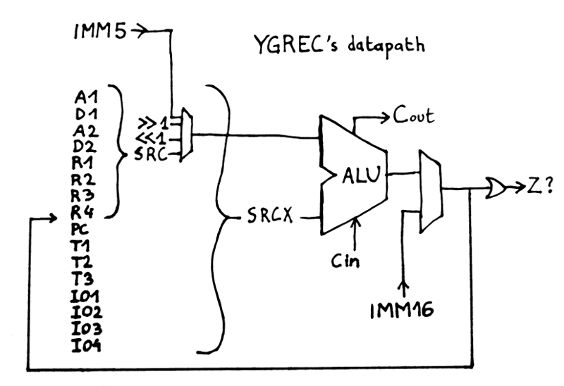
Even a kid could understand that, right ? :-)
I haven't included the rest, like DRAM, PROM, clock, tree drivers...
On 2nd thought : let's scrap the IMM16 MUX at the end of the ALU. Instead, send "Pass SRC" to the ROP2 and we're done. However the gain is not significant and probably negative because
- IMM5 is sign-extended but IMM16 is transmitted as is. That's 11 MUX2 to select the MSB.
- the ROP2/ALU control signals must be "overdriven" : that's 5 more MUX
No relay has been saved but it's more compatible with a transistorized implementation.
Here is the new version : it looks even more simple !
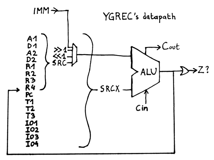
Of course it's simple because I have taken a lot out of the picture but this gives you a "programmer's view.
Update : I added the PC in the datapath in 7. The Program Counter's circuit
Discussions
Become a Hackaday.io Member
Create an account to leave a comment. Already have an account? Log In.