 Yann Guidon / YGDES
The incrementer and the ALU are becoming the critical parts of the whole system and the length of the carry chain will affect the operating speed. In itself, the clock speed is not a goal (the thing is already sooo sloooow that you can see it think, which is all the point). However, the faster it runs, the faster it can scan and refresh the memory, which is quit a big deal. If I can manage to get 25IPS (approx 2× faster than the Harvard Mark II), then it still requires 10 seconds to scan 256 words, 1/3 of a minute to refresh the whole 512 words of DRAM. And refresh only happens when the processor doesn't access the memory, a full refresh could last one minute. I haven't yet evaluated the retention time of the DRAM but I feel I'm pushing the design in uncharted territories.
With 100µF capacitance, a 1µA leakage will make a time constant of approximately 100s which, depending on parts tolerance, where the leaks go, the actual rate and current of leakage etc. This is pretty close to the above quoted minute and I'm concerned.
The new instruction register introduces a "latched sensor" which has several interesting benefits but one major consequence over the overal design: the processor is now pipelined, with fetch, execution and DRAM cycles being overlapped. The clock sequencing is pretty simple now : 2 phases, which directly drive the temporary storage caps of the DFF. There is no funky sub-cycles anymore. The complexity is now relegated to the software because data access and jumps are now delayed. I should add a 25th instruction bit to tell the program sequencer to wait for one more cycle until data are available...
The speed is now limited by two main factors:
- the carry chain delay
- the time to fully charge the latching capacitors of the DFF
As I have already examined, the charge time depends on several factors, such as the charging voltage and the series resistance, so they can be somewhat adapted. The carry chain length is however a more structural problem. If a relay switches in 4ms, a chain of 4 relays will need 16ms to propagate, and I would ideally keep it under 20ms. Add to this about 10ms to charge the caps then switch them to the coil, and we have about 30ms of cycle time, or 30Hz.
To reach this speed, the critical datapath must be under 6 relays.
My problem is that the РЭС has a rather low fanout capability and it wouldn't drive 15 coil loads. I guess a reasonable fanout is 4, though I remember I estimated 3 when I started the #SPDT16: 16-bits arithmetic unit with relays project.
Of course, less fanout is better and the LSB relay (bit 0) will take all the heat, vibrations and load so it must be particularly carefully designed (or it might break).
@Tony Robinson has explored a particularly interesting approach: a OR-chain made of diodes that could greatly accelerate the propagation in my case. However the diode drops are significant, let's assume 0.8V for the 1N4148 and this becomes quicly impractical. And the fanout problem is not solved, the first diode will take all the current to drive all the coils in the chain... I could cheat by using high power Schottky diodes though but it wouldn't remove the high current draw when all the chain is ON.
Apparently I am forced to use a segmented approach. Naturally the 16-bits incrementer is split into 4 equally sized segments, but not identical: the LSB have a high fanout while the MSB have a high fanin. I can also mix with a diode here and there to reduce the complexity/size/cost/consumption a bit. With this scheme, the propagation time might drop to 2 coils delay, but the incrementer will use a LOT of relays...
The linear approach is slow, the fast approach (O(n²)) is prohibitive, so a hybrid approach is considered, using 4-bits segments. Hopefully, the fanout is not excessive and the cascade time is 4 coils (in the 16ms range).
I have a drawing in my head, I'll need to refine it...
Update 20170420: I made the pictures !
So it started with the carry chain of Tony Robinson's idea of using diodes to accelerate carry propagation. But this is not adapted for relays. I came up with this version that solves the diode drop problem.
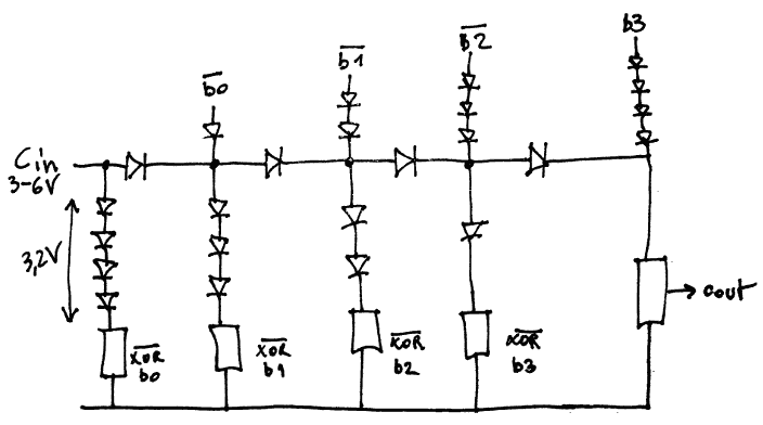
However this circuit is
- wasteful (a lot of energy is lost in the "balancing" diodes)
- still plagued with the fanout problem (Cin drives up to 5 coils in parallel, or 7 ohms of equivalent load)
So I applied the same recipe as with other parts of the system: when parallel becomes an issue, go serial!
And it looks promising: using a 12V rail, the coils can be connected in series with the diodes. It started like this:
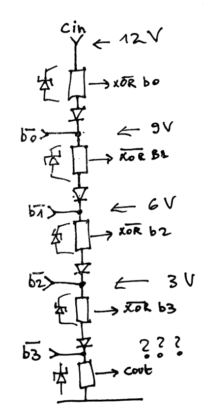
5 relays and 4 diodes in series don't work but it's promising. With only 3 bits and one more relay for the level translation, the voltages look very good:
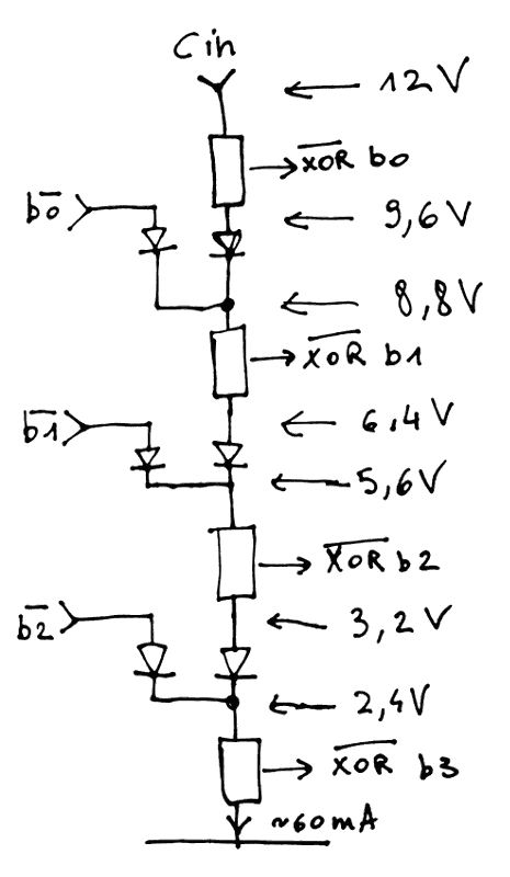
This method is energy efficient, even though there is almost always current flowing in most of the chain. Only 2 diodes per bit are used (and almost always dissipating). With the proper voltages, I even wonder if it's possible to get rid of the diodes. But since the voltages fall almost perfectly with the existing rails, I'll keep 4 coils in series.
I'm OK with 3 bits per strings because 16 bits is 3×5 (+1) so the propagation delay is only slightly worse than with 4 bits per string and the design looks reliable and uses few relays.
The actual carry chain looks like this:
- b0 is always /b0 so there is nothing to see here.
- the first Cin comes from the inverted b0 and computes b1, b2 and b3 (and Cout)
- then b4, b5, b6 and Cout
- then b7, b8, b9 and Cout
- then b10, b11, b12 and Cout
- then b13, b14, b15 and some error flag ?
The carry chain itself has 4 coils of delay but a 5th coil delay comes from the XOR. Still: 5 coils delay is just what's needed to provide the PC+1 just in time at the end of the cycle.
Mission accomplished? Not so fast! There are 2 new problems...
- How do I generate 9.6V for the 3rd relay ??
- How do I even get the high voltage levels out of the flip-flops ?
...
The additional rail is not hard to get : just use a dumb resistor (typical 39 ohms) tied to +12V. That's overall 5 resistors. There are other rails : 6.6V and 3.3V with perfectly suitable voltage.
I don't like to waste power so I thought about putting a relay coil instead of the resistor but what would it control ? There is no need to try to speed things up because the critical datapath is just right.
The 2nd question is more difficult. The output of PC is 3.3V level, going to the datapath, and also looping back to the DFF. This is good for the bottom of the diode ladder but the two other levels require some sort of level translation. This uses one more relay...
To speed things up, the relay can be in series with the 2 other latch relays but this is not a balanced configuration (the number of relays is odd). A resistor is necessary but a 4th relay might be necessary to drive the PROM address decoders. DPDT relays are soooo handy......
Overall, for each bit of the PC, we have :
- 1 relay to select the source (result or PC+1)
- 1 clock relay (with its capacitor)
- 1 relay for the XOR
- 4 relays for latching and fanout (2×loopback@6V, datapath@3V, PROM@12V ?)
= 7 relays ....... that's about 112 relays for PC, running mainly at 6V, and 32 diodes.
Discussions
Become a Hackaday.io Member
Create an account to leave a comment. Already have an account? Log In.
Cheating, but have you looked into transmission gate multiplexers?
https://www.ti.com/product/TMUX1134
Since you got to convert logic levels anyway...
Are you sure? yes | no
it's worse than cheating, it's lazy ;-)
The only compromises I made are the use of some diodes, and RES-60 and RES-64 for certain cases where the RES-15 can't work well.
At this moment, 4 years after this log, I'm back on the subject and have found a good looking chain topology, though for a modular incrementer. The magic of circuitjs makes it come to life on your browser: https://hackaday.io/project/159762-hardware-assembler-emui/log/194972-relay-based-frequency-divider
this is going to evolve, of course, to handle 12V series connections (to reduce the current) and because it's only an incrementer and not an adder. Also look at #YGREC8 which is way more up-to-date (and smaller) :-)
Are you sure? yes | no
Carry chain is easy with diode bridge coil XOR.
If XOR(A,B) proves the inputs un-alike, let carry propagate through.
If XOR(A,B) proves same, let either of the inputs propagate instead.
Doesn't matter which one, since already proved both are same.
Gives a perfect Generate for 1+1, but Kill for the case of 0+0...
Are you sure? yes | no
For a Zuse adder, there’s nothing special for the carry chain - have you considered that one?
Are you sure? yes | no
It's an option of course but I am limited to SPDT and Konrad hacked his own relays from scrap, which expanded his choices (and reduced the reliability)
Are you sure? yes | no