 Yann Guidon / YGDES
Here is one of the 24 bits of the instruction register.
3 relays each amount to 72 relays.
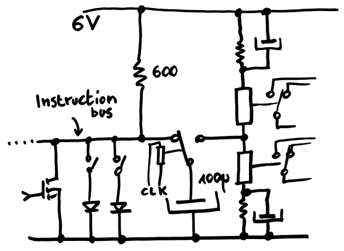
The instruction bus uses 6V signaling to provide more swing into the capacitor, but not enough to damage the diodes (the KOA diode networks are limited to 7V in reverse polarity).
The sensor is made more sensitive by charging the capacitor with a higher voltage swing, bringing more charge to upset the coils. The middle point is centered by resistors, but large capacitors are required to keep the ends at a somewhat constant voltage. I got a stock of 1500µ capacitors so the swing ratio is at least 1/10.
The reduction of the current on the instruction bus is pretty important. If 60mA per bit was required, then a INV instruction (FFFFFFh) would draw 1.5A ! Hopefully this is now reduced to about 10mA, or 240mA for a full FFFFFFh instruction. This increases the longevity of the parts...
I'll have to prototype the above circuit !
Discussions
Become a Hackaday.io Member
Create an account to leave a comment. Already have an account? Log In.
Hi Yann,
If you have a Harvard machine, the PC will drive the program ROM all the time, and the instruction is available all the time at the output of the ROM. You might need to amplify the instruction, but (depending on the timing design of your machine) it might not be needed to have an instruction register (or latch).
Are you sure? yes | no
In this case, amplification is quite necessary, and latching it (accumulation then release through the coils) is a natural consequence. This creates a delay slot for jumps/calls, only one cycle so it's manageable.
I'm considering a half-phase shift trick for the DRAM to prevent delays.
However, clock speed is more important than instruction rate because the major issue is the refresh of the DRAM.
Are you sure? yes | no