 Yann Guidon / YGDES
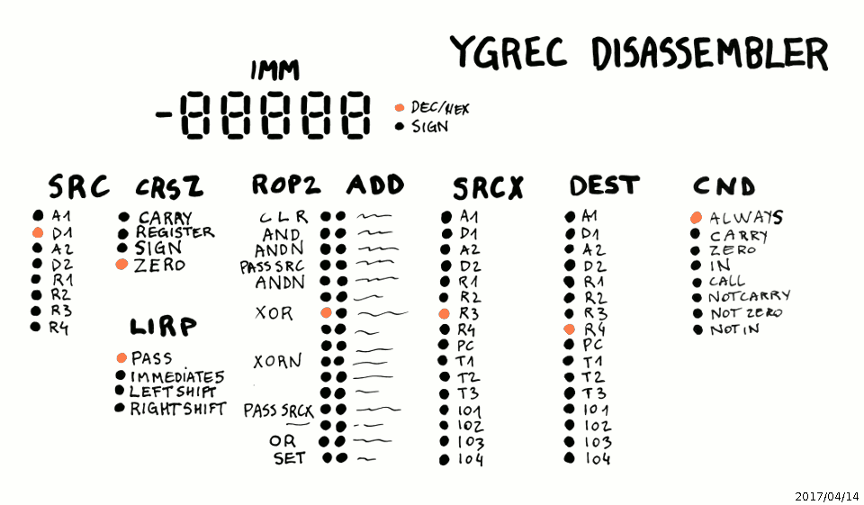
After I completed the instruction switch panel, came the necessity to build the corollary: the panel that displays the instructions. I had a sketch but soon realised that the system used too many relays, making it both power-hungry and expensive. For example, the hexadecimal display with 4 digits requires 16×4 LEDs, no big deal, but also 15×4=60 relays to demultiplex the nibbles ! According to the display:
 there are
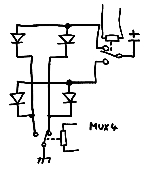
- 2 × MUX4 (3 relays each)
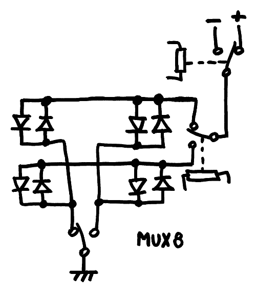
- 2 × MUX8 (7 relays each)
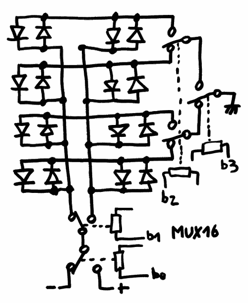
- 2+4 × MUX16 (15 relays each)
- 1 × MUX32 (31 relays)
so the total is 141 relays, or 4 boxes of 36 pieces, with some pretty high fanouts (despite knowing strategies to balance them). This also uses a significant amount of PCB surface !
Discussing with @Dr. Cockroach about a similar concern with his #IO - The Inside Out Cardboard Computer - bis, (he uses a servo to point to one out of 16 numbers), I came to the conclusion that I should try a galvanometer. It's reasonably cheap and simple : a R/2R network driven by one relay per bit, and you're done.
However readability is not great and despite having found a 0-15V model (which is great for displaying from 0 to F), this causes the other problem of getting 15V (actually 16 !) in the first place... See the rest in the log Relay DAC
Then I realised that I got the initial MUX thing wrong.
The light dots can be either a LED (which is a diode) or a Glühbirnchen (which can be wired in series with a diode). I couldn't find suitable flipdot elements (too large, harder to drive) so let's stick to diody elements.
MUX4 isn't really a problem with only 3 relays but... This can be reduced to only two ! The LED can be arranged in a 2×2 array with one relay for the rows and another for the columns. It's only one relay saved per MUX4 but the fanin is just one coil per bit.
Total : 2×2 + 2×3 + 7 + 6×5 = 47 (instead of 141), this is totally reasonable....
I'm concerned however about the imbalance of fan-in between the various bits, this makes the design more complex. I could add resistors in series to balance the single coil signals but it's wasteful...
Another concern is the digital display : bipolar matrices don't ease 7-segments decoding. I'm thinking about the #"Lixie", an LED alternative to the Nixie Tube approach but I'd need a tiny version and readability would be worse than the large displays...
20170323 : OK, another simplification : what if the digital display was in octal ? This would save 4 relays (though unlike Seymour Cray I'm not an octal guy).
Even more desirable: more input signals will have a fan-in of one coil.
This leaves a couple of MUX16 and one MUX32...
I'm trying to come up with a "4th dimension", and I was thinking about voltage or current. It's easy to turn a light above a higher threshold (add some diodes in series) but not to turn another off. Unless there is a relay somewhere... So this is going in the direction of using an input relay to amplify the signal.
I'm also thinking about an optical system that could replace the Lixie...
Discussions
Become a Hackaday.io Member
Create an account to leave a comment. Already have an account? Log In.