 Yann Guidon / YGDES
Development with this kind of machine is "bare-metal". I'm simply tired of writing emulators and simulators, and people actually don't need much to get started : forget Eclipse or Emacs, just take some paper and pens. You can program a computer with something to input the instructions, and something else to read/decode the binary into human-readable form.
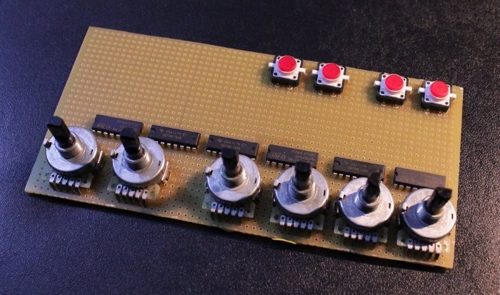
Following my experience with the #Discrete YASEP, I have decided to create a "hardware assembler/disassembler", using this kind of technology (sans the TTL ICs, see #Quick & Dirty Frequency Generator ):
A set of two boards are connected to the instruction bus :
- The first board inputs data using knobs, in a manner that follows the instruction's logic and structure, and writes the corresponding bits on the bus.
- The second board reads the bus and displays the value, in a human-readable way (that is : with LEDs and maybe a #DYPLED)
If the user can take over the buses (instruction address bus, instruction read bus, ...), they can examine the program, input arbitrary instructions, single-step through routines, modify the memory and check the execution.
The assembler board provides one switch or rotating knob for each field :
- 4 knobs for the IMM16 field
- one for each source and destination register field
- one for the condition
- some switches and sliding switches to select modes and options
For example :
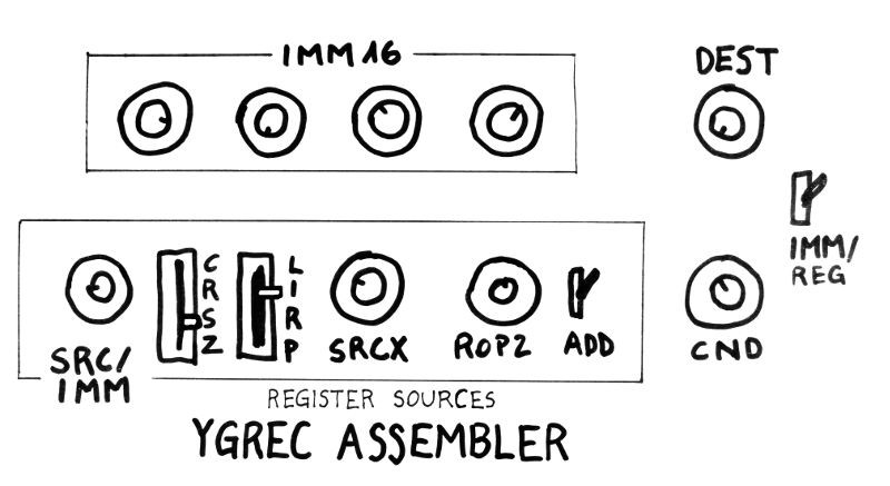
Note that the values of each position are not all marked because they are displayed in the disassembler board :
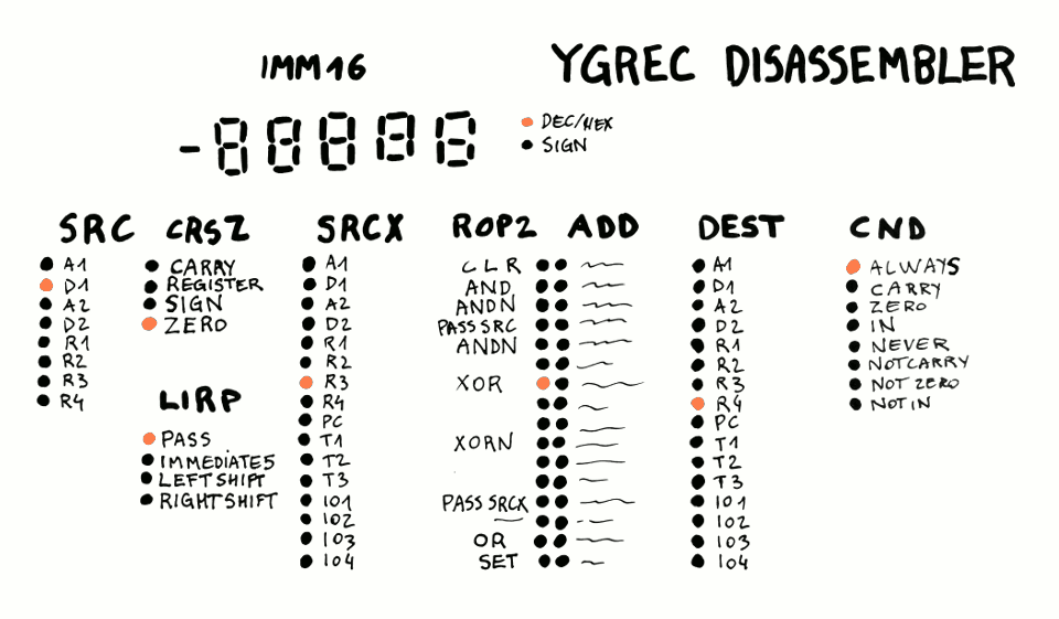
Little lamps show the value of the current instruction. In this example, we see the instruction "D1 XOR R3 => R4"
The disassembler board is always connected to the instruction read bus so you can see the machine's thoughts as it runs... But both the assembler and disassembler must be modular because they will be reused for the next implementations in various technologies :-)
Discussions
Become a Hackaday.io Member
Create an account to leave a comment. Already have an account? Log In.