 Yann Guidon / YGDES
While I had the camera, I thought it was a good opportunity to show you some more raw parts, introduce you to them and discuss what's in store, and why.
I already have optocouplers. They're used to extract the clock and eventual loss of AC current.

CNY17-3 is rated at 5KV isolation, the LED typically draws 1.4V with a current transfer ratio of 100-200% and the NPN phototransistor can sustain 60mA.
Detecting AC does not require much bandwidth, on the contrary. Not much current is needed either, it will only control a RC network.
So it might be a bit overkill and may not detect very short losses of power, but still better than counting on the PSU module to discharge through all the parts. The discharge time must be measured, by the way
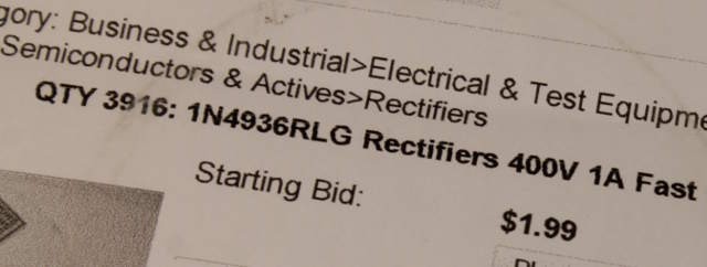
I got diodes too. A 4K reel of 1N4936, from a time when I used to play the auction game. Starting price was indeed low, I don't remember how much it went in the end but shipping from Canada was far from free...
But I have quite a lot of 1A 400V diodes. They are used in the primary/input, to shield the optocoupler against reverse voltages and as a sort of Zener.
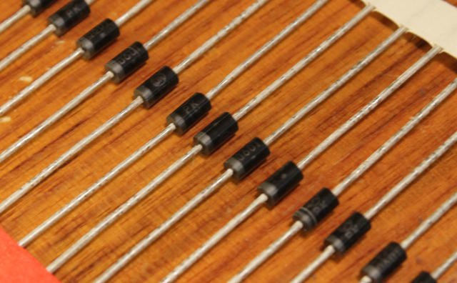
I won't use 2 but 3 in series, because the drop voltage has some variability, depending on the current. The remaining voltage will be dropped by a resistor to protect and limit the current through the optocoupler (value TBD)
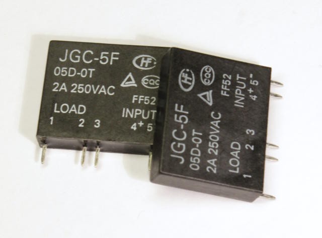
I have a few SSR to switch the current.
The JGC-5F here is a 5V, zero-switch relay that is appropriate for small to medium loads. But it's unsutiable for high currents: the 2A are equivalent to max. 500W which is easily exceeded in applications where this project matters.
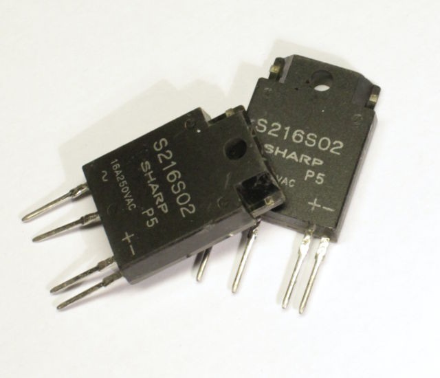
I employed the tested and trusted SHARP S216S02, that I still have in stock. I don't know where to find more, it's discontinued and I don't know a good and cheap replacement.
When looking at the full curves and taking into account the derating, the advertised 16A rating is not fully realised without "proper heatsinking", meaning that a dissipator is required if you want to operate up to 50°C. If your electrical dispatch box is outdoors and exposed to the sun, sunrays can heat the insides and affect the parts...
In the harsh conditions, the part is only safe for 2A. Which is far from the continuous 10A rating of the circuit breaker.
In a precedent project, I used a dirty solution : use two of them in parallel to provide 4A, or almost 1KW per channel. That was a bad choice, if I believe some weird behaviours. I prefer to use only one with a heatsink, despite the added complexity. I don't have heatsinks yet however.
Oh, by the way: the pins are fragile. Like, don't bend them. Adding a heatsink will complicate the fabrication. The added challenge is the small pitch : 18mm is not enough to fit the SSR, the heatsink and the required gap to let the air flow...
Ironically, the SIP package of the S216S02 is about 18.5mm wide so it's not possible to preserve the 18mm pitch. The pitch must be 36mm (to allow the use of classic busbars).
36×4 channels makes a 144mm PCB : not the smallest possible but I'll miniaturize later...
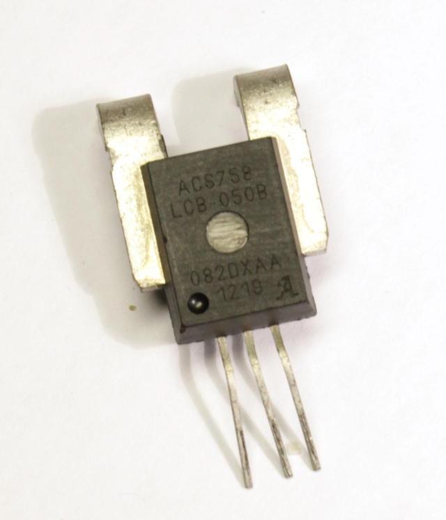
I also got some AC high-current sensors but they won't be used. The circuit breakers are there to detect the faults.
Now that I have got the parts and more data about dimensions, it's time to draw the schematics.
Discussions
Become a Hackaday.io Member
Create an account to leave a comment. Already have an account? Log In.