 Patrick Van Oosterwijck
Since electrically this project is an offshoot and/or combination of the #LiFePO4wered/Pi and #LiFePO4wered/18650 projects, the current hardware I already have makes a good platform to do experiments on.
In fact, one of my recent experiments, which now really belongs here more than on the LiFePO4wered/Pi project page, was already documented in this LiFePO4wered/Pi project log. I was testing the TI TPS71235P, a new high power boost converter I intend to use for this project. In fact, now that I will be having enough space for a resistive divider to set the output voltage, I intend to use the TPS71236P instead, which will allow me to configure the output voltage myself instead of using a fixed 5.1V. Since efficiency and current capability get better when there is less difference between the input and output voltage, I want to have a default output of 5V but provide a solder jumper that allows the user to reduce the voltage to 4V for more efficient operation if their system allows it.
In the current physical form factor of the LiFePO4wered/Pi, the booster was able to support a continuous current of 1.6A at 5.1V, and as this thermal image shows, the inability to shed heat was the limiting factor that made the thermal protection kick in at higher currents:
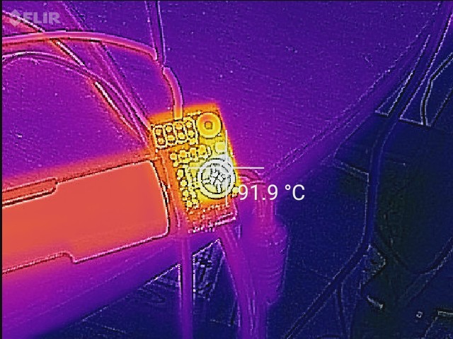
The image clearly shows that the heat stays very concentrated in the little PCB. My hope is that with the LiFePO4wered/Pi+ going to a larger PCB with 2 oz copper, this heat can be sinked away from the chip more effectively and I hope to be able to support at least 2A continuous output current.
Another goal for the LiFePO4wered/Pi+ is to make the maximum load current independent of the charge current. To do this, I intend to split the current sense resistor on the charger and connect the load to the midpoint. By choosing the right resistor values, the charge current can be limited to a safe value for the battery while the load can pull significantly higher current directly from the power source. The principle is demonstrated in the graph below:
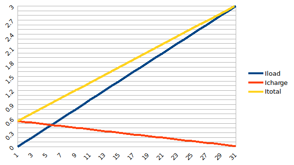
In this case for the 14500 cell, the charge current under no load is about 550 mA, but as the load current increases, the total current pulled from the input goes up to accommodate the load. As the load current gets higher, it takes more and more from the input until eventually at 3A there is no charge current left for the cell and the cell will start to provide current instead.
You may have noted that I'm designing the charger for 3A instead of the 2A that I mentioned above for the load current. This is because the boost converter trades current for voltage, so that even with ideal components and no losses, a load current of 2A at 5V requires an input current of 3.33A at 3V. So I really should go for a higher current than 3A for the charger, but the test below was done at 3A charge current and has me worried to go any higher:
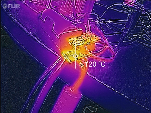
The problem is that the charger uses an asynchronous buck design and the Schottky diode always drops around 0.5V at high current, making it dissipate a lot of power. I need to see what temperatures I get on a bigger PCB before I start thinking about pushing the charger current any higher. I may also need to see if I can find a synchronous charger instead, but it's hard to beat the CN3801 I use currently on value.
Also, the CN3801 is not a low leakage chip, and leaks quite a lot of current from the battery when it's not charging. That's why I currently use a MOSFET to disconnect the battery from the charger when it's not being charged, similar to what can be seen in the #LiFePO4wered/Solar1 schematic (Q4), which reduces the leakage to less than I can measure (<1uA). The problem is that the current topology doesn't work with the split current sense resistor scheme described above. So I need to disconnect the battery differently.
I did an experiment yesterday with moving the MOSFET up to right after the inductor instead:
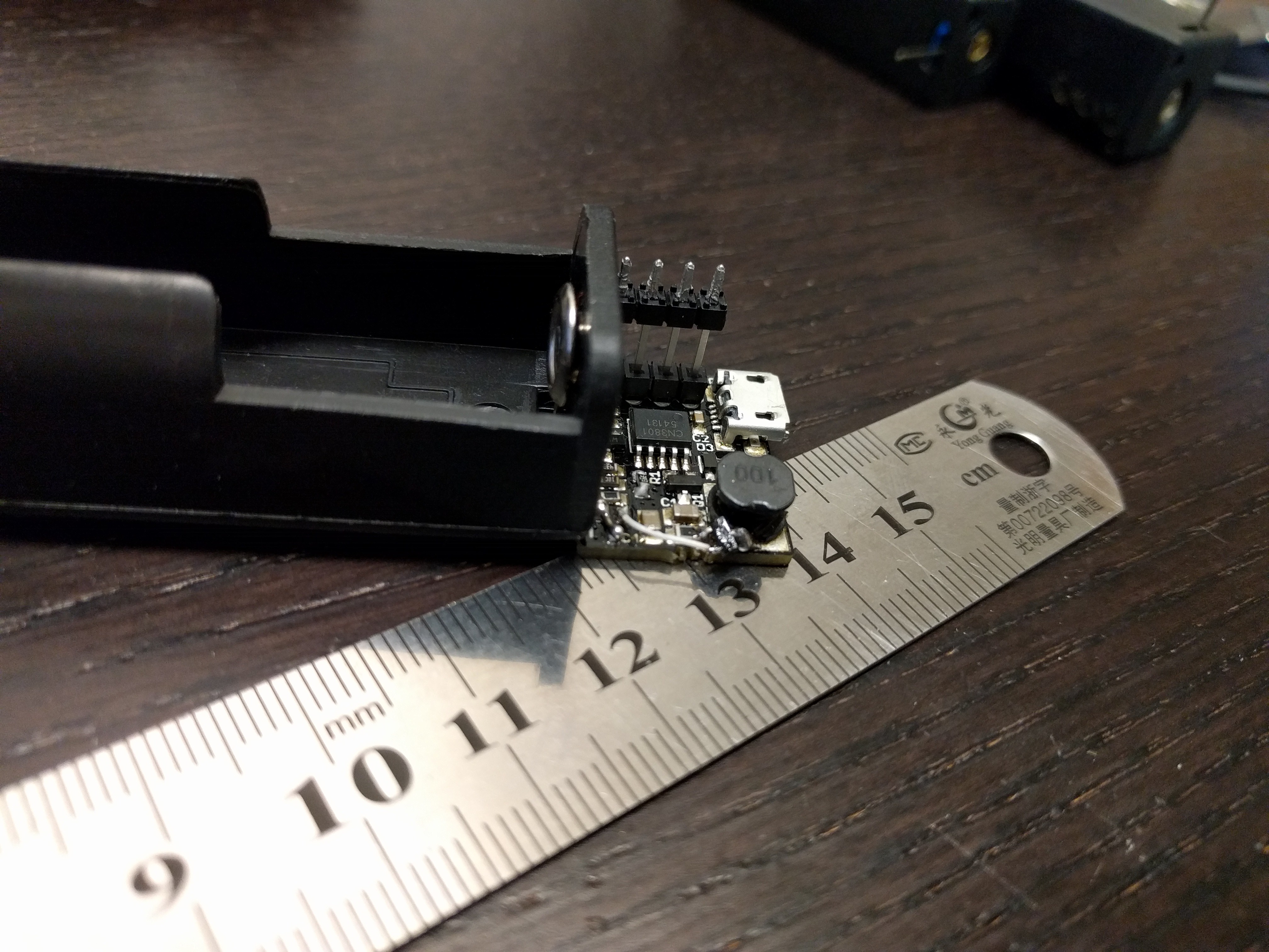
Hackish, but it did the job well enough to test the concept. :) This reduced the leakage from 100+uA (with no battery disconnect) to less than 10uA, current that is still leaking into the CSP and BAT pins of the CN3801. I hope to fix this by adding some BSS84 MOSFETs in the connections to those pins, but testing that will have to wait until I have my first prototype.
Discussions
Become a Hackaday.io Member
Create an account to leave a comment. Already have an account? Log In.