 Patrick Van Oosterwijck
I decided to build up my first prototypes of the LiFePO4wered/Pi+ today. Since I wanted to do all 3 boards I received from OSH Park, and there are quite a lot of components, I figured using solder paste and reflow was the way to go instead of manual soldering.
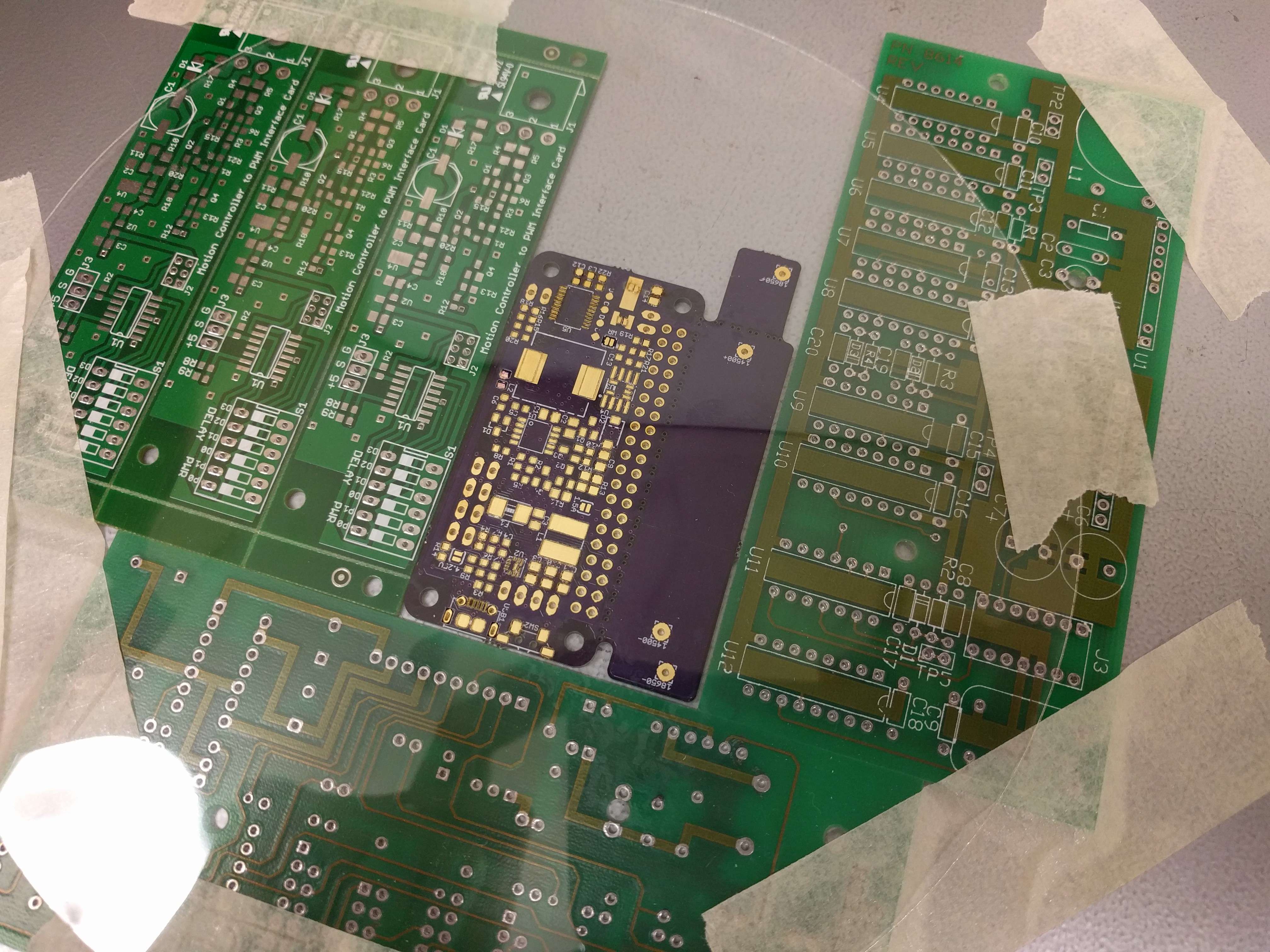
I had not ordered a stencil so I used the laser cutter at the Tinkermill to cut my own stencil from plastic film. It never turns out as well as the professional ones you can buy, but it's free and usable. :) Below is a picture of the stencil over a bare PCB:
Time to apply solder paste:
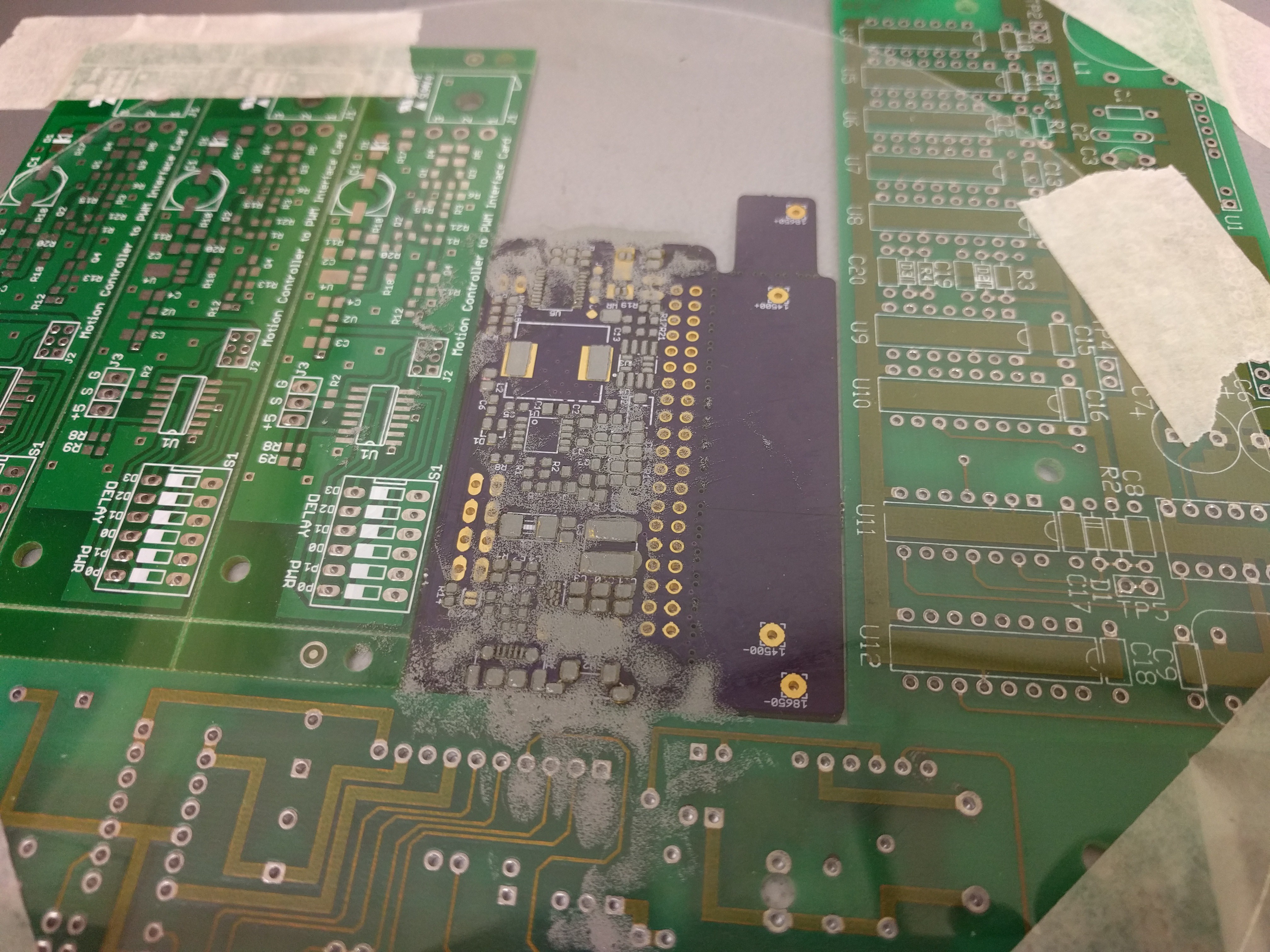
The result with the stencil removed is fairly decent, even for the tiny and weird TPS61236P boost converter pads:
I decided to paste all 3 boards and then build them up in batch:
The disadvantage of doing this is that the paste tends to dry out during the long build. Placing the components took around 2 hours and the paste was definitely getting dry, but it seems to have had no ill effect. Here are the boards with all components placed except the inductors:
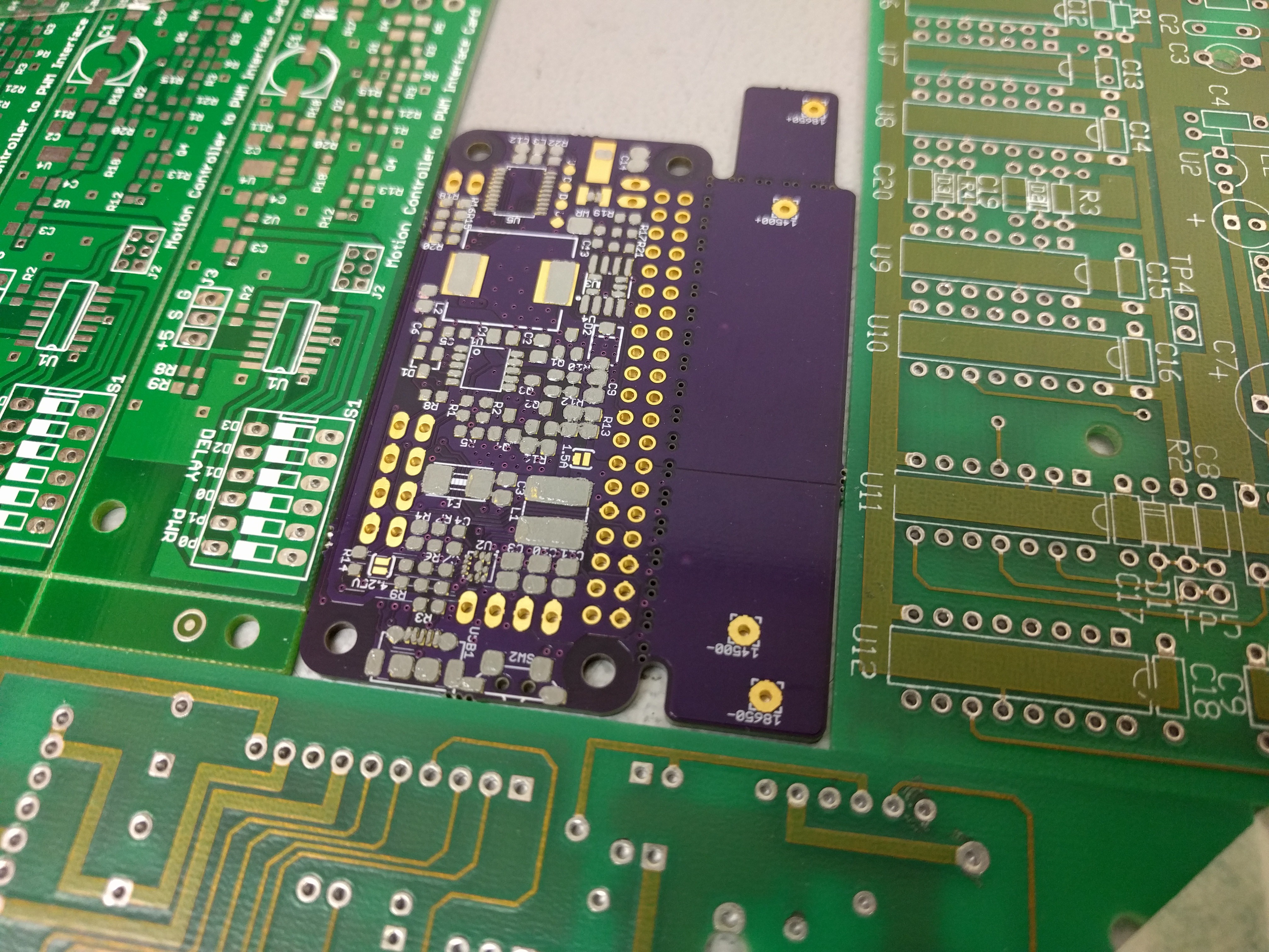
And here's a closer shot, ready to go into the reflow oven:
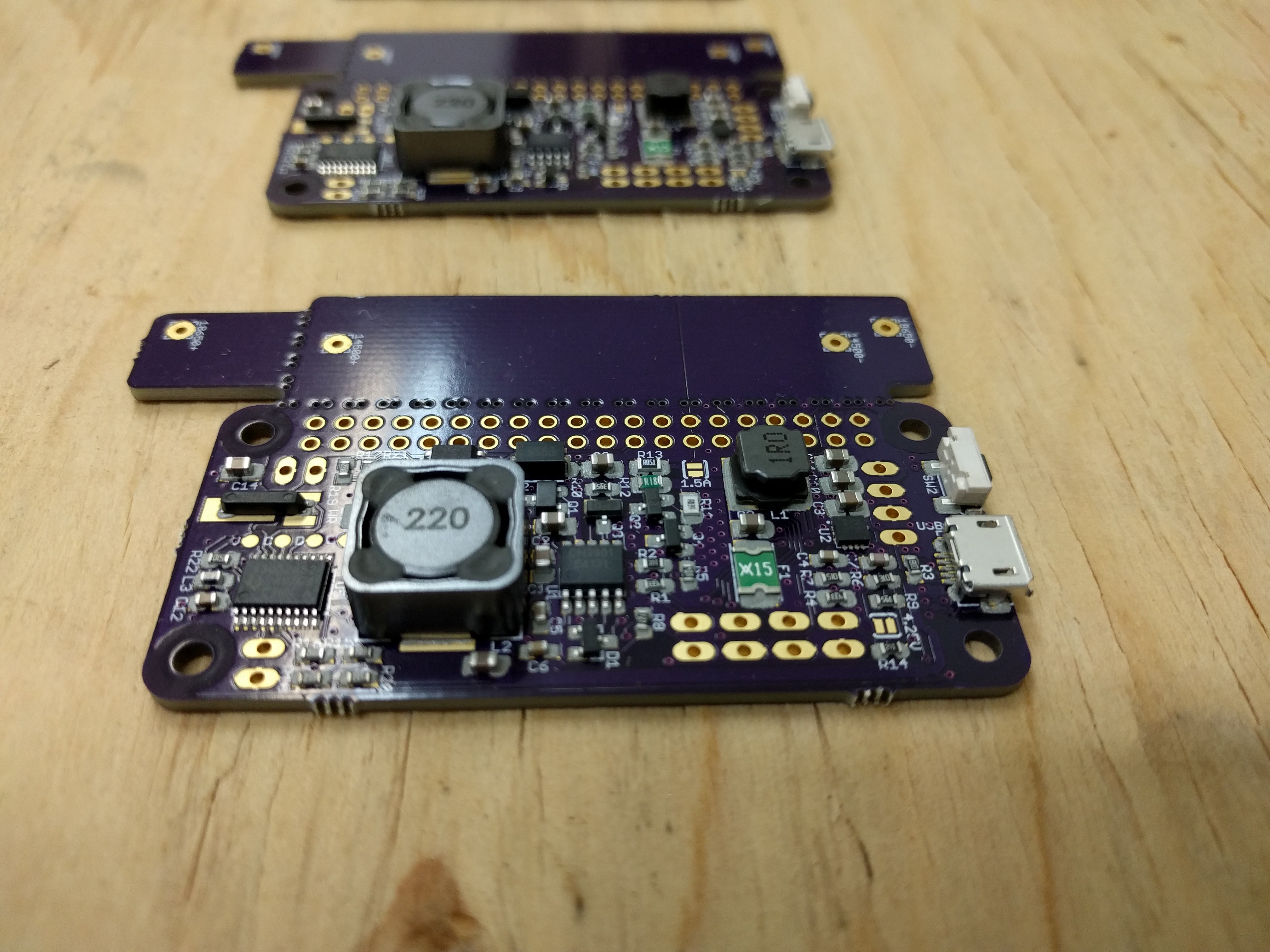
Here's the first board after reflow:
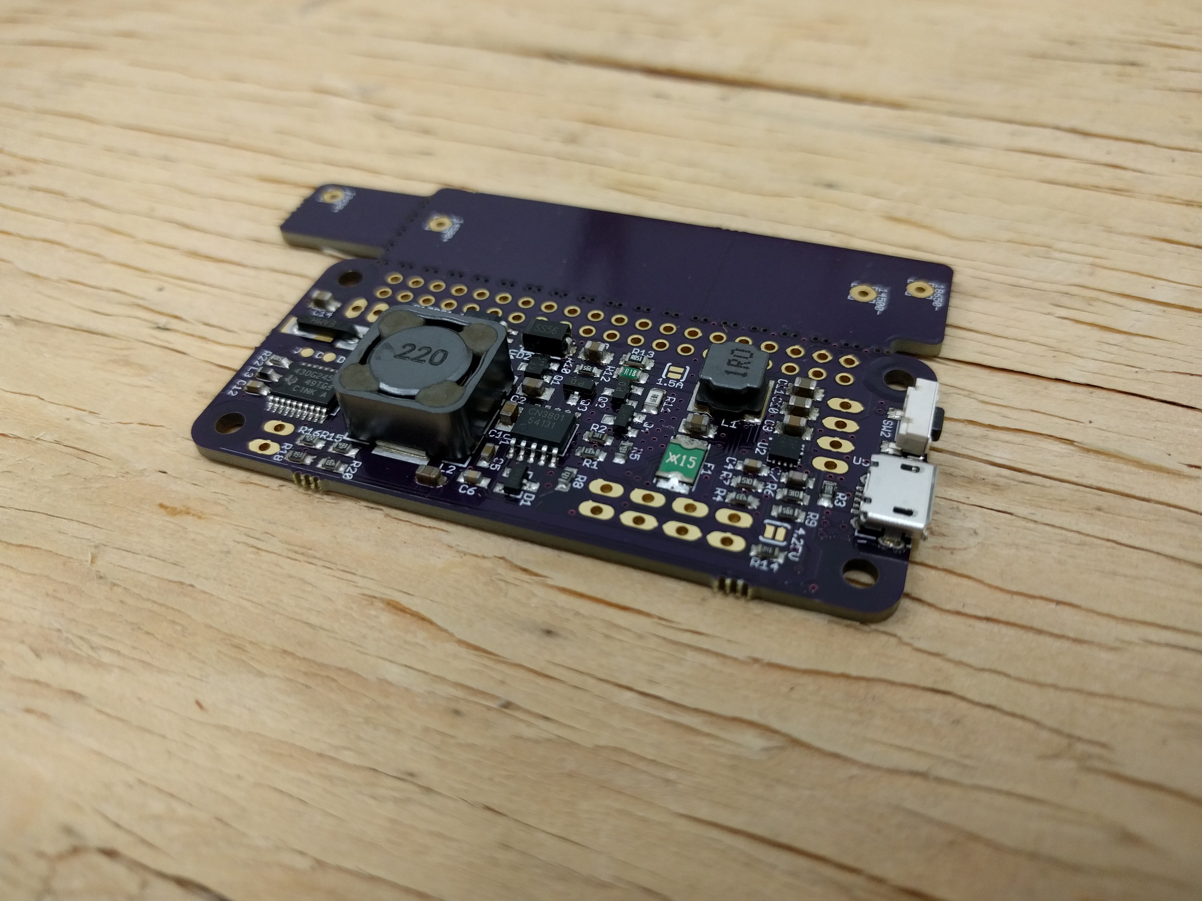
Looking good! :) Even the TPS61236P connections seem to have soldered fine. I was a little worried because the stencil wasn't exactly accurate for those tiny pads.
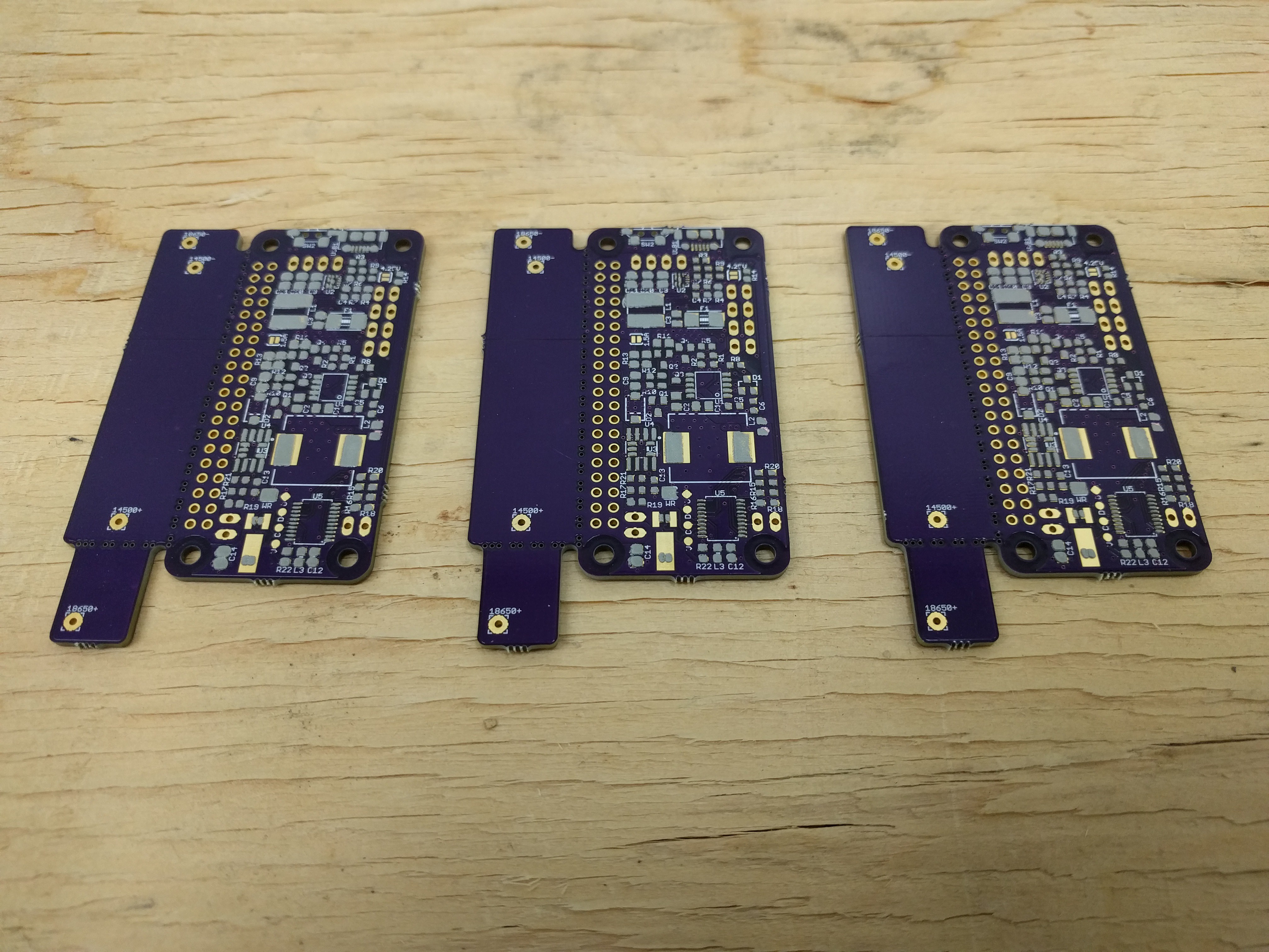
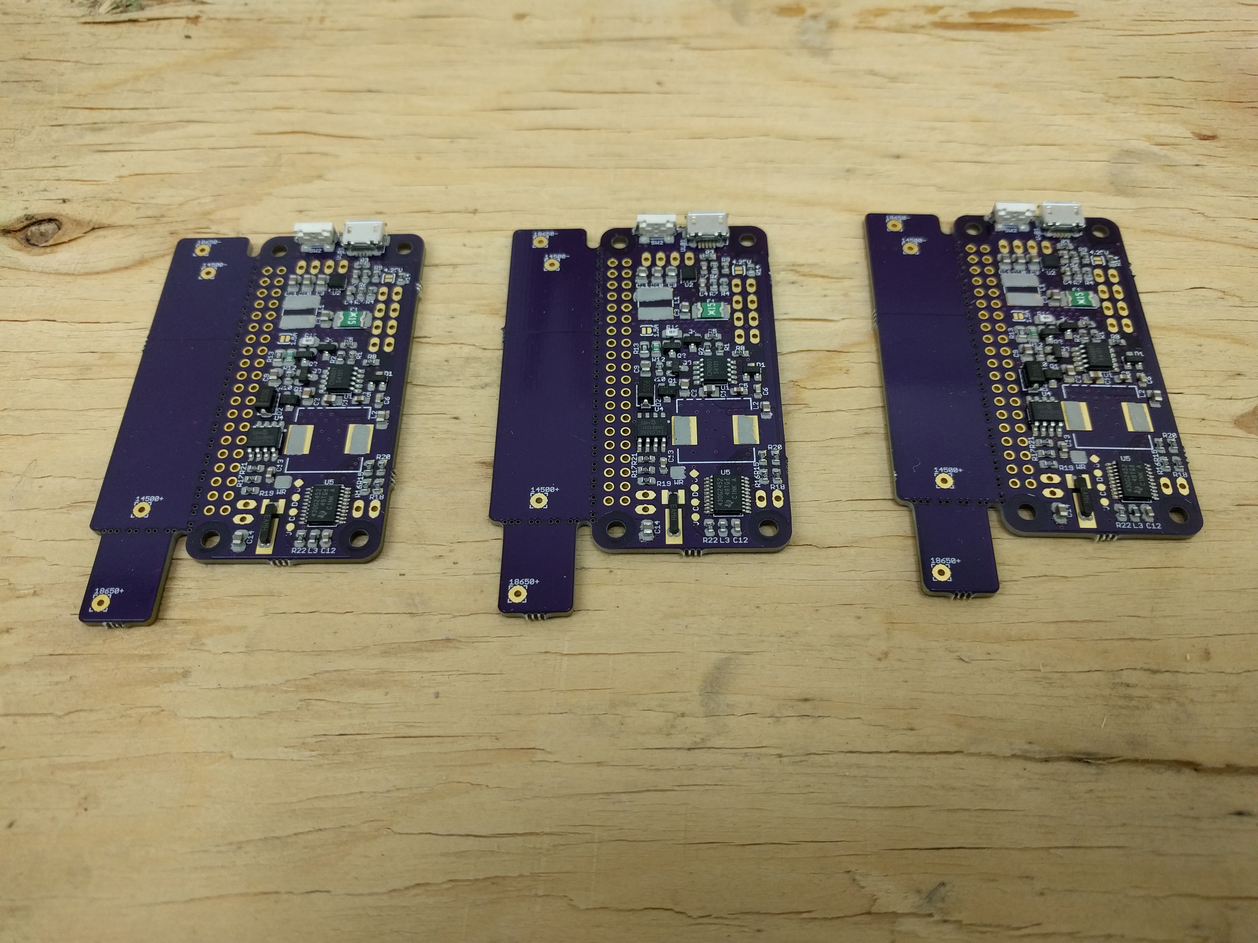
Here are all three boards done:
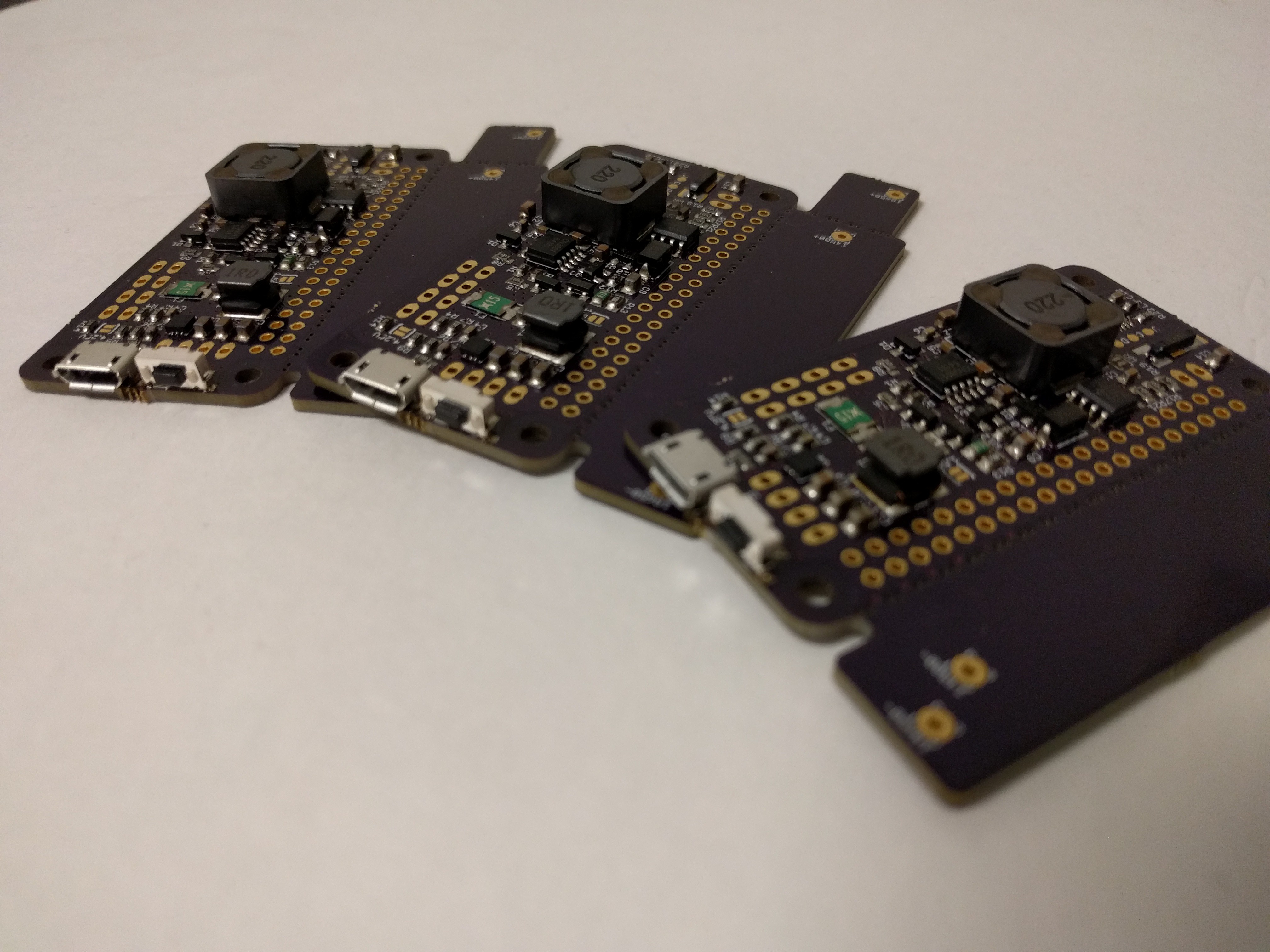
I still need to add the LEDs on the other side of the boards, and maybe a top button. As you can see, there is a side-facing button already on the boards but I want to evaluate different options such as side-facing and up-facing. I also need to add the 40-pin GPIO headers and battery holders.
Then I need to take the existing #LiFePO4wered/Pi firmware package and port it to this new platform. This new design needed more pins than were available on the micro I was using before, so I'm using a different part from the same family and some pin assignments have changed. Plus, I need the firmware to sample a physical button instead of a touch button and use the 32kHz crystal instead of the internal RC oscillator.
Discussions
Become a Hackaday.io Member
Create an account to leave a comment. Already have an account? Log In.