 Patrick Van Oosterwijck
One concern I had was that when using the small 14500 size battery, the current sense resistor that limits the charge current also is in series with the load when running from the battery. My concern was that it would drop so much voltage that the software would decide that the battery was depleted and shut down. This is, of course, not a problem since the battery voltage is measured directly at the battery, and not after the sense resistor. But I had temporarily forgotten that. :)
So I did a test where I used a MOSFET to bypass the 0.18 ohm resistor when the input (charge) voltage was not present. I wanted to see if it affected run time from the small battery. This is still a valid test, because the boost converter does see lower input voltage due to the voltage drop across the sense resistor, so its efficiency might go down.
The test was done with a Pi3 with 4 cores @ 100% and an active SSH connection over WiFi. Here are graphs of the battery voltage in mV:
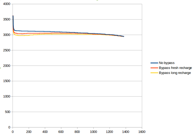
Oddly, the results look better without the bypass. The worst result was after a recharge a day ago, the voltage would droop and threaten to fall below the shutdown threshold, but then recovered. The longest run time is without any bypass, and was about 23 minutes.
I don't know for sure what caused the initial droop, it could be a chemical effect in the battery when charging wasn't recent and ion mobility may be lower. I will have to do a little more testing on that since it comes dangerously close to the shutdown threshold.
Overall this is good, the little battery did hold up so it's promising as a solution for those who are looking for UPS functionality and just want enough power to get through a clean shutdown. The Pi was pulling ~950mA at 5V, which translates to about 1.6A at the battery voltage. Testing with my electronic load seems to indicate 1.2A output current is the limit for the small cell, at which point the boost converter output droops to ~4.85V, still within the USB spec.
Discussions
Become a Hackaday.io Member
Create an account to leave a comment. Already have an account? Log In.