 Patrick Van Oosterwijck
So I built my prototypes last week and I have been testing them since, I just hadn't found the time to write about it yet. ;) Here are some shots of the build process, first pasted with components:
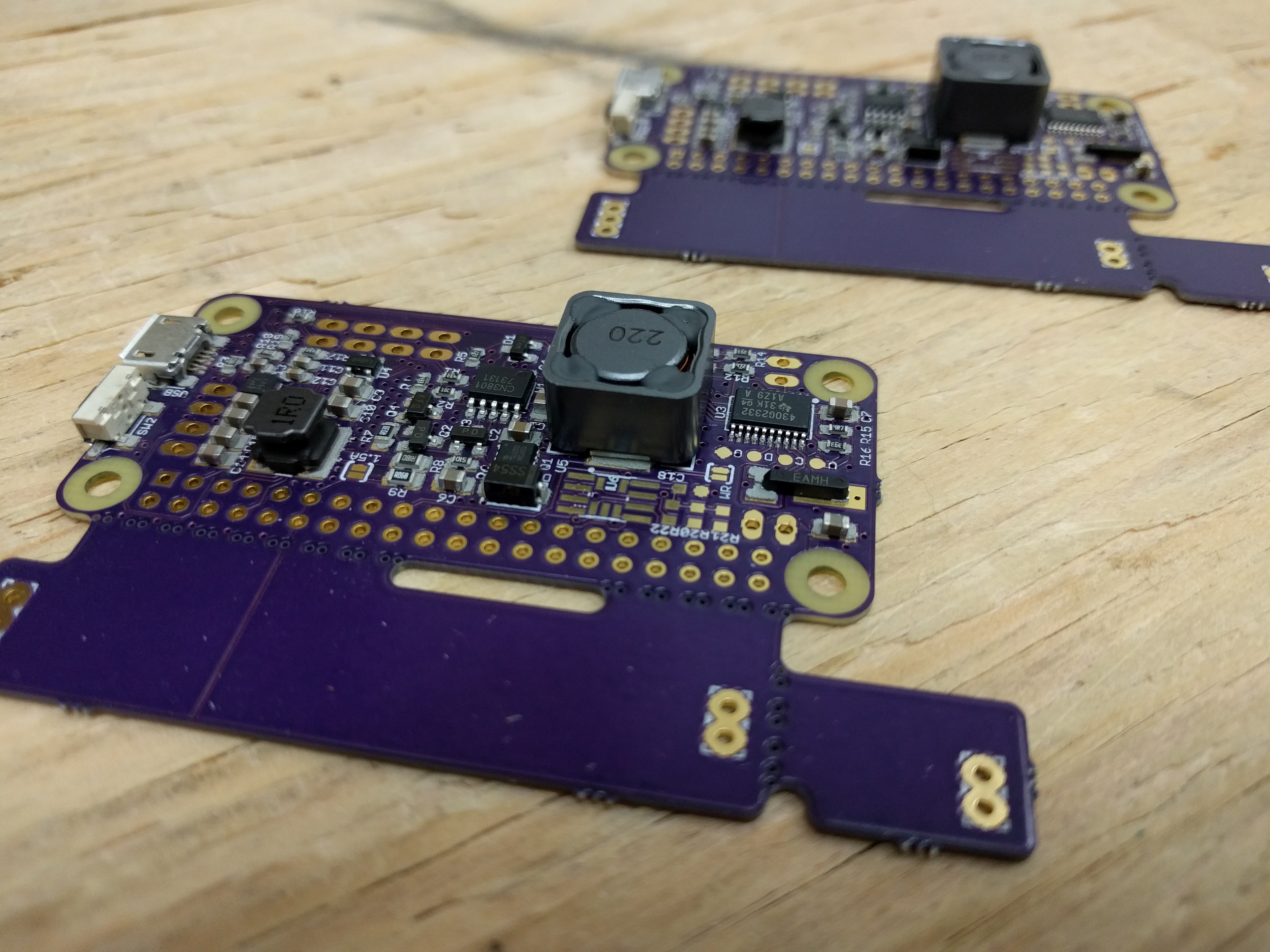
And out of the reflow oven:
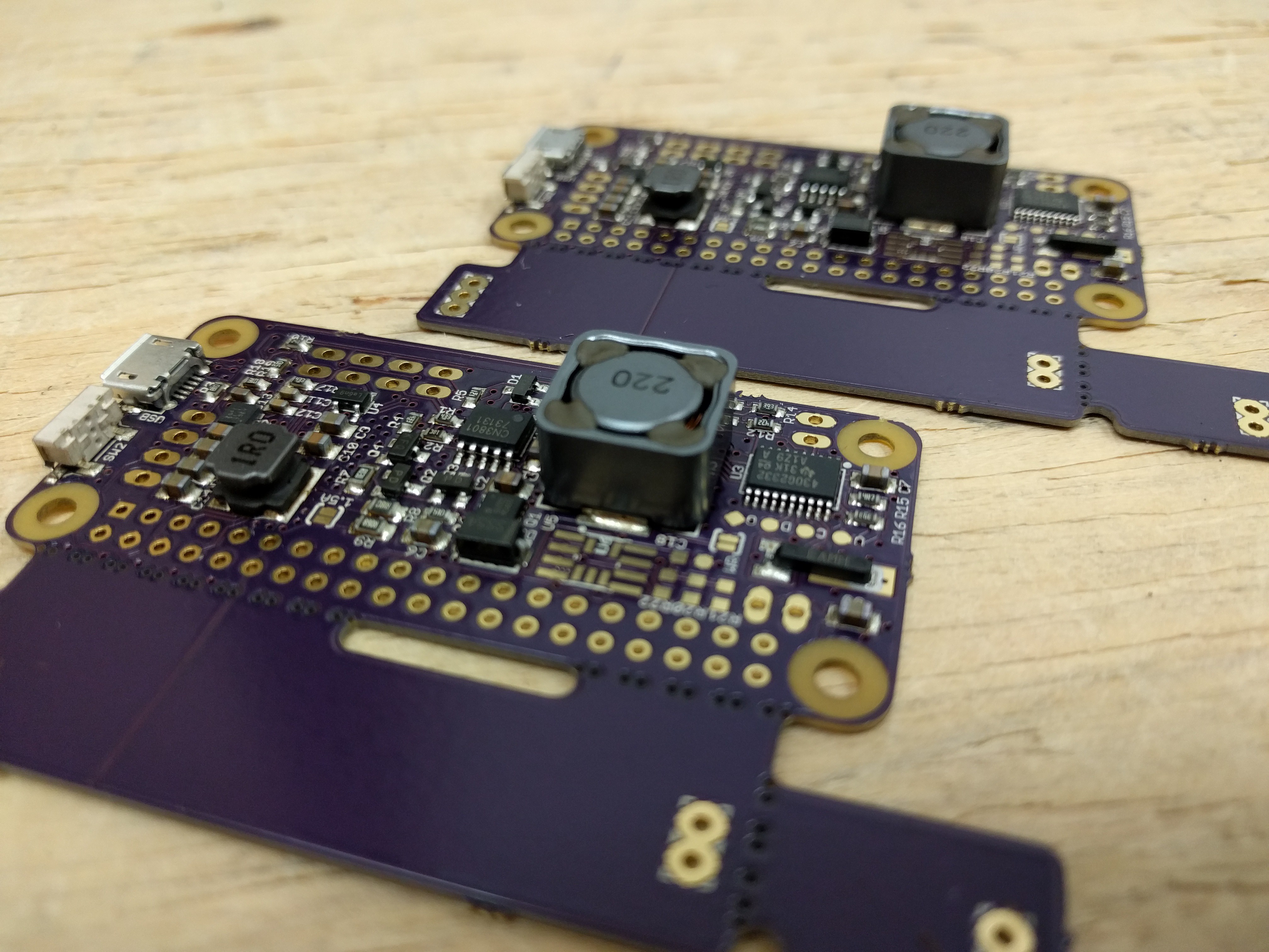
This is how it looks all built up and with a 18650 battery and installed on a Pi:
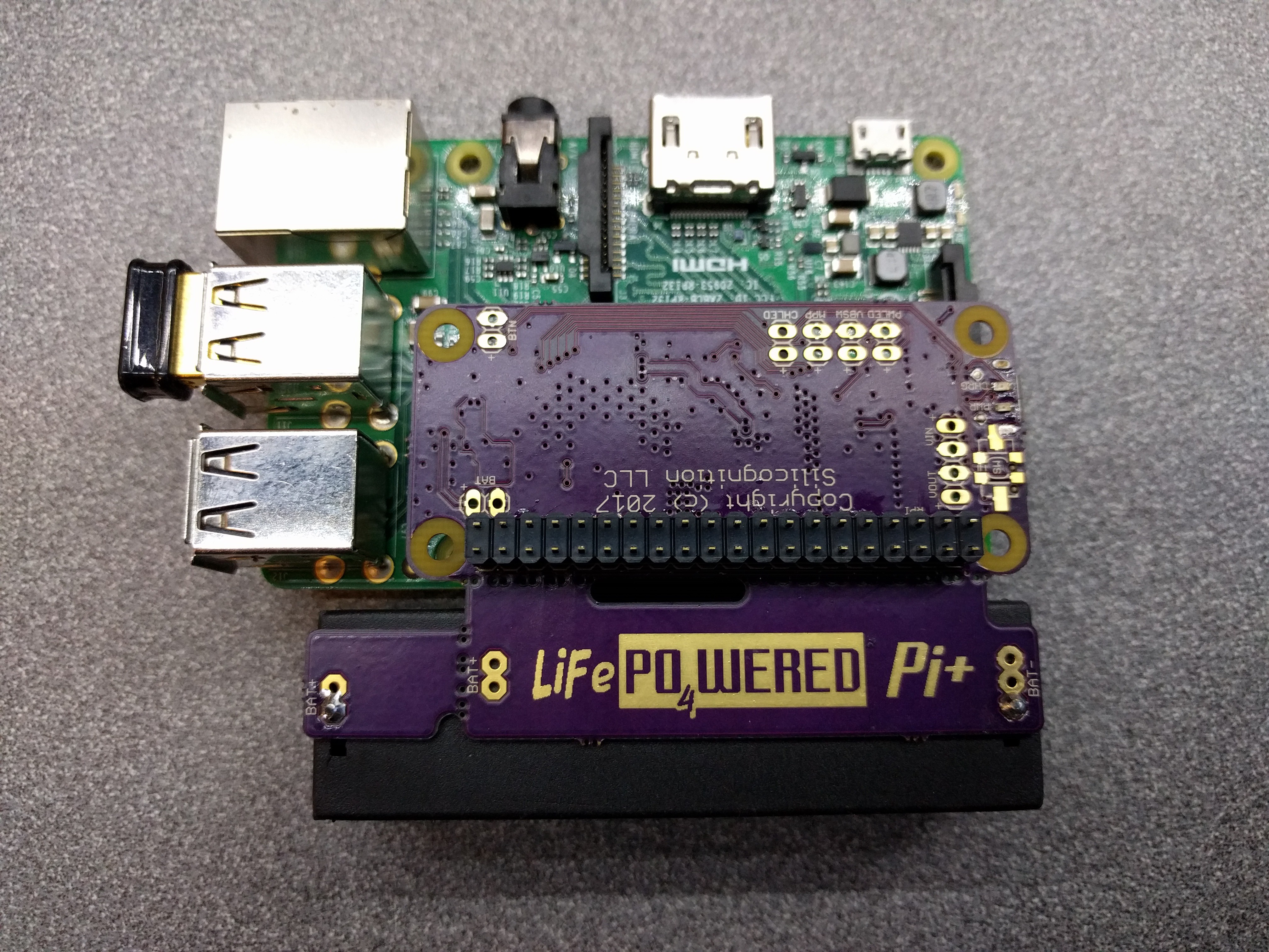
As you can see, there is accommodation for both 18650 and 14500 size batteries, and there are two positions for each size battery holder: one to be as compact as possible (battery close to the Pi) and one that provides a little distance to allow installation in standard cases while having the battery outside, as in this example with a 14500 cell in the official Pi case:

The case only needed minor modification to fit. Of course without making a hole, the USB connector and power button aren't accessible. But it's easy enough to make a hole and if you don't want to, you can enable auto boot / auto shutdown and solder input power to the Vin pads.
I started "easy" on the testing and everything was working great. Even with a Pi 3 running with 4 cores at 100%, things hardly got warm. Power down current, while keeping RTC, is still only around 4uA.
Then I pulled out my electronic load and started testing at 2A load current. The new switching MOSFET seemed to be handling it well, but oddly the pass transistor that previously wasn't giving me any trouble was getting really hot! Then I looked at it a little closer:
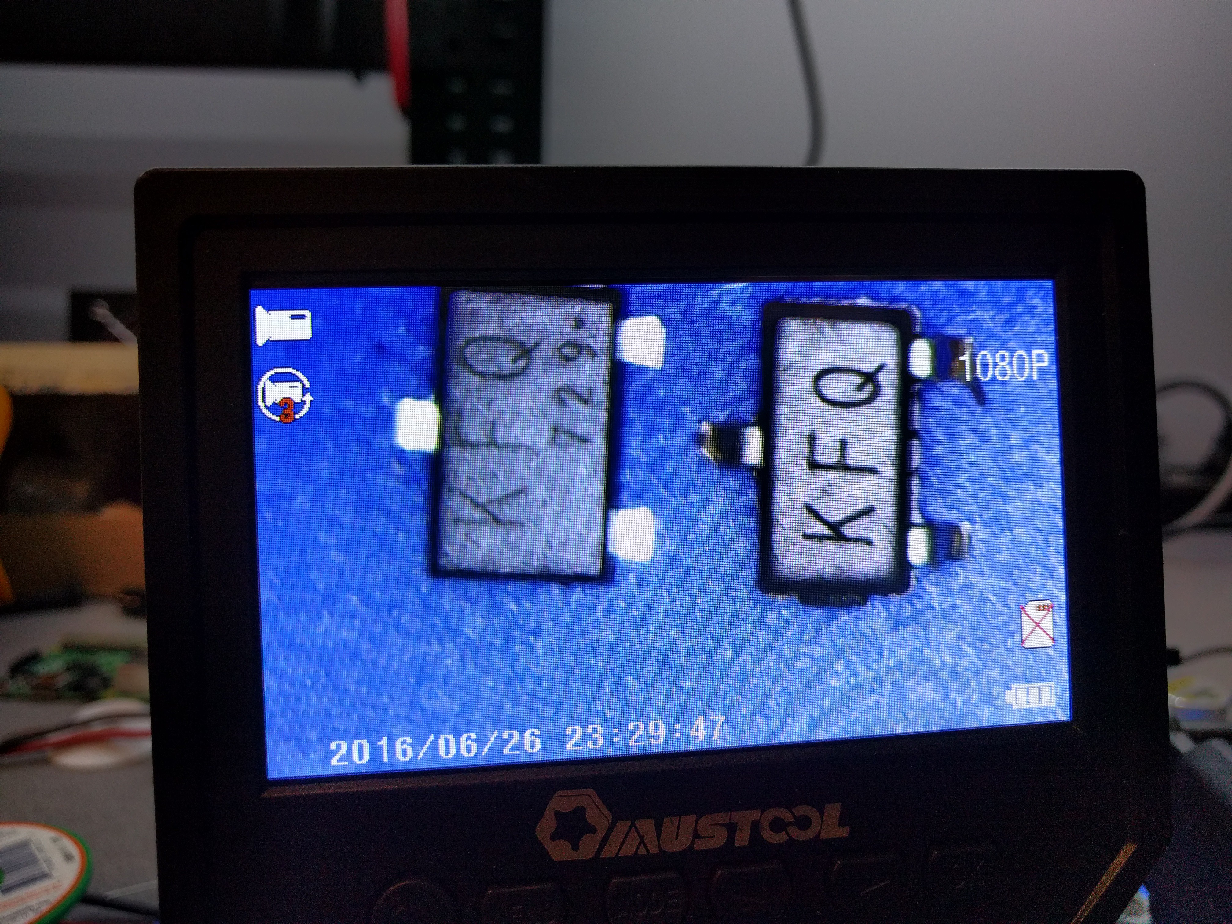
The device on the right was the one that was in the board and that I had sourced from China. The one on the left was bought earlier from a US distributor. The real part has a bigger body (probably to fit a bigger chip inside), and the leads come out flat on the bottom for less resistance and better heat transfer. The fake part looks like a normal SOT23. I really should have spotted that during assembly. Turns out the fake part works as a "power MOSFET" as well, but it has an RdsON of about 130 mohm, while the genuine part has an RdsON of 20 mohm or less. So it was burning way too much power at 2A load (2A load at 5V means over 4A from the battery do to the lower voltage and losses in conversion).
So I replaced the fake parts with real ones and the overheating went away. I have been doing high load testing since then and can confirm that the heat dissipation is low enough to allow UPS operation at 2A load current without active cooling! But it's close, I can't get much higher before the boost converter kills the output because of thermal protection, and probably inside a case it will overheat sooner.
But seriously, if you're building a system that is going to make a Pi burn 10W, you better have some fans for active cooling! :)
I also tried what would happen at higher currents with active cooling:
This ran for quite a while (several hours) at 2.5A load, eventually the boost converter did a thermal shutdown. I haven't determined the limit since it doesn't matter: the spec is 2A.
Also, remember my infamous project log where I burned up a transistor while testing at 20V input voltage? Well, I've been testing this for over 8 hours now and it's working beautifully. Yes, it gets hot, but no thermal shutdown, and nothing that some active cooling can't handle.
If you're wondering why there aren't pretty thermal pictures in here, it's because I don't have convenient access right now. Next week I should be getting my own thermal camera and then I'll be able to get some real data. :) I'm pretty confident in the design though, so I'm ordering production panels.
Discussions
Become a Hackaday.io Member
Create an account to leave a comment. Already have an account? Log In.