 Patrick Van Oosterwijck
Had a little bit of a scare this morning. I arrived at my office and noticed that the LiFePO4wered/Pi+ I had intended to be running at 1.8A load over the weekend had turned off. Off as in "the micro had determined the battery voltage was too low and switched to off state". This was especially weird since the charge LED was on, and the input voltage was around 5.5V. My first thought was of course "oh no, what has died?" :)
I measured the voltage across the current sense resistors and it was zero V. With 5.5V on the input and the charge LED on, it seemed "obvious" that something on the LiFePO4wered/Pi+ was faulty. So I moved the setup over to my other workbench where most of my measurement tools live so I could scope what was going on, plugged it in to the power supply that was there and... the voltage across the current sense resistors was 120mV as it should be! Everything was normal.
Ok, move it back to the test bench, plug it in there... and 0V across the current sense resistors! What the heck? Was it the location? Brought the supply from the other bench over... 120mV. Seems something is wrong with the power supply on the test bench, but how can that be, since I measure 5.5V on the input? Let's scope it:
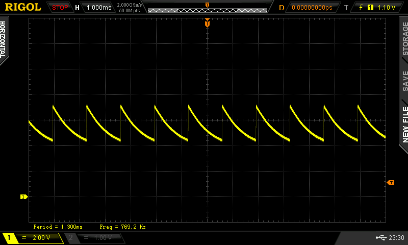
Ah I see. The power supply did go bad. Whenever the charger on the LiFePO4wered/Pi+ starts to draw power, the voltage collapses. So the charger gives up, and the voltage returns. Over and over, without actually providing any charge current.
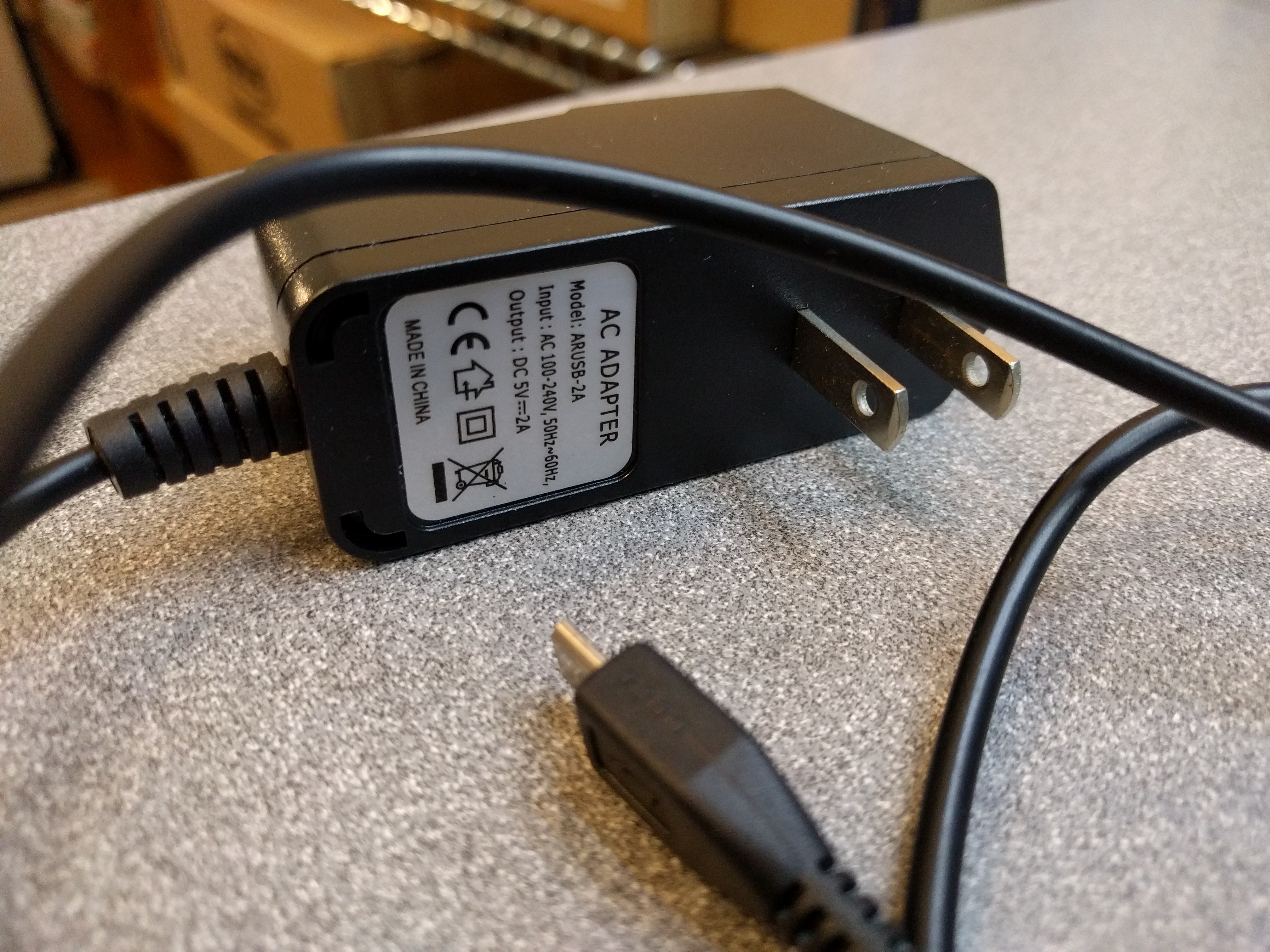
Now this was not my cheapest power supply from eBay or AliExpress. I got this one as part of a Pi Zero kit at Microcenter. It's rated 2A.
Choosing the right power supply is going to be important for those who will want to push the LiFePO4wered/Pi+ to its limits. Due to the nature of power conversion, the LiFePO4wered/Pi+'s efficiency is not 100% but around 75% instead at 2A load (much better at lower load). The charge converter uses an asynchronous topology and has around 85% efficiency, the boost converter has around 90% efficiency in those conditions. Combine them, and you're around 75%. This means that to support a 2A load, the power supply will have to provide around 2.7A.
My experience is that most 5V wall warts are not able to do that. Even if they are rated at 2.5A, they start to sag seriously around 2A. Since the LiFePO4wered/Pi+ has a smart charger that can be used with weak supplies and solar panels, it will automatically reduce charge current to ensure the input voltage will not sag below 4.65V (the default MPP set point). So I'm sure I'm going to get complaints from people because they are using a lousy supply that sags but they will blame the LiFePO4wered/Pi+ for not working as a UPS at high load. :)
That is a protection feature though to prevent the power supply from being overloaded. Therefore it's odd that the one shown above died on me.
On another note, I am now talking to PCB manufacturers to have production panels made. I've finalized the design and decided to have the PCB manufacturer take care of doing the panellization this time. Here's the final design they are working with:
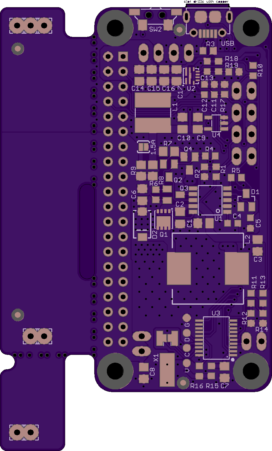
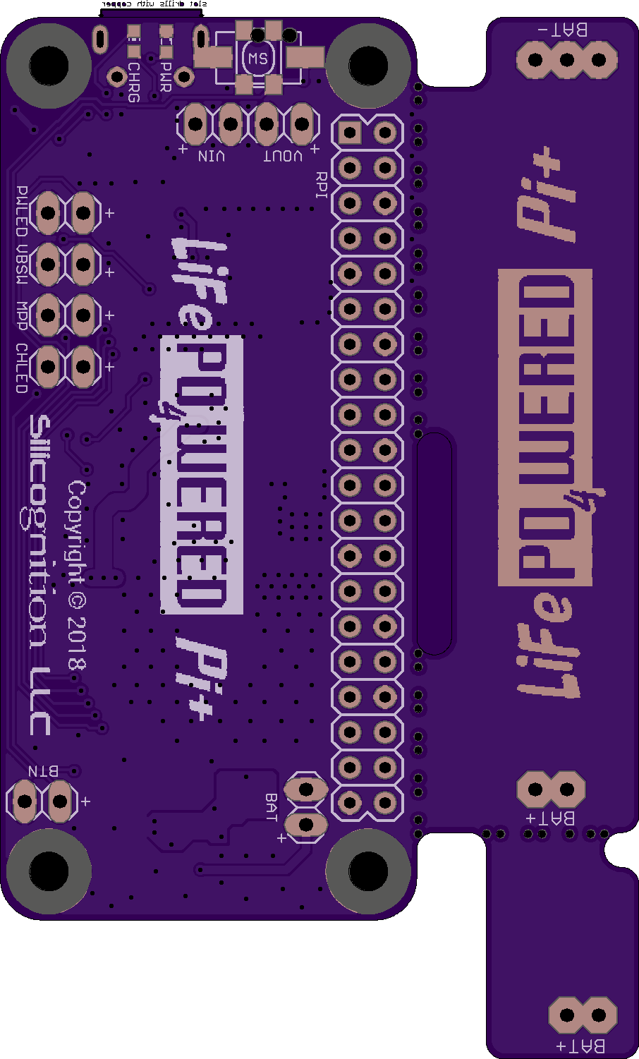
As you can see, I improved the silkscreen with some custom artwork, removed the unused HAT EEPROM and related components and put some more copper there instead for better heat dispersion. The logo on the battery holder part is made by removing solder mask, so in the final product it will be silver in a black background, which will hopefully look cool when it sticks out of a case. :)
Discussions
Become a Hackaday.io Member
Create an account to leave a comment. Already have an account? Log In.
Wow, that's instructive.
Are you sure? yes | no