 Orlando Hoilett
Heart Rate Monitoring with the MAX30101
Heart rate is a measure of how many times our heart beats per minute and is usually represented in just that "beats per minute" or BPM. Photoplethysmography is a very popular technique for measuring heart rate. Photoplethysmography takes two popular forms, reflectance photoplethysmography and transmission photoplethysmogrpahy. In transmission photoplethysmography, a light shines through an extremity such as a finger and a detector measures the amount of light that passes through. When the heart pumps blood through the body, we notice a momentary increase in blood volume in the fingers. As a result, the amount of light that passes through the finger changes with this changing blood volume and is detected by the photodetector. In transmission photoplethysmography, instead of measuring the amount of light that passes through the finger, we measure the amount of light that reflects off the finger. The MAX30101 by Maxim Integrated is in a specialized integrated circuit that is able to perform reflectance photoplethysmography. The MAX30101 contains three light-emitting diodes, one red, one infrared, and one green. The IC also contains a photodetector and contains all the circuitry necessary to process the recorded signal in order to detect heart beats and subsequently, calculate heart rate. By using this specialized IC, we can detect heartbeats and subsequently, calculate heart rate.
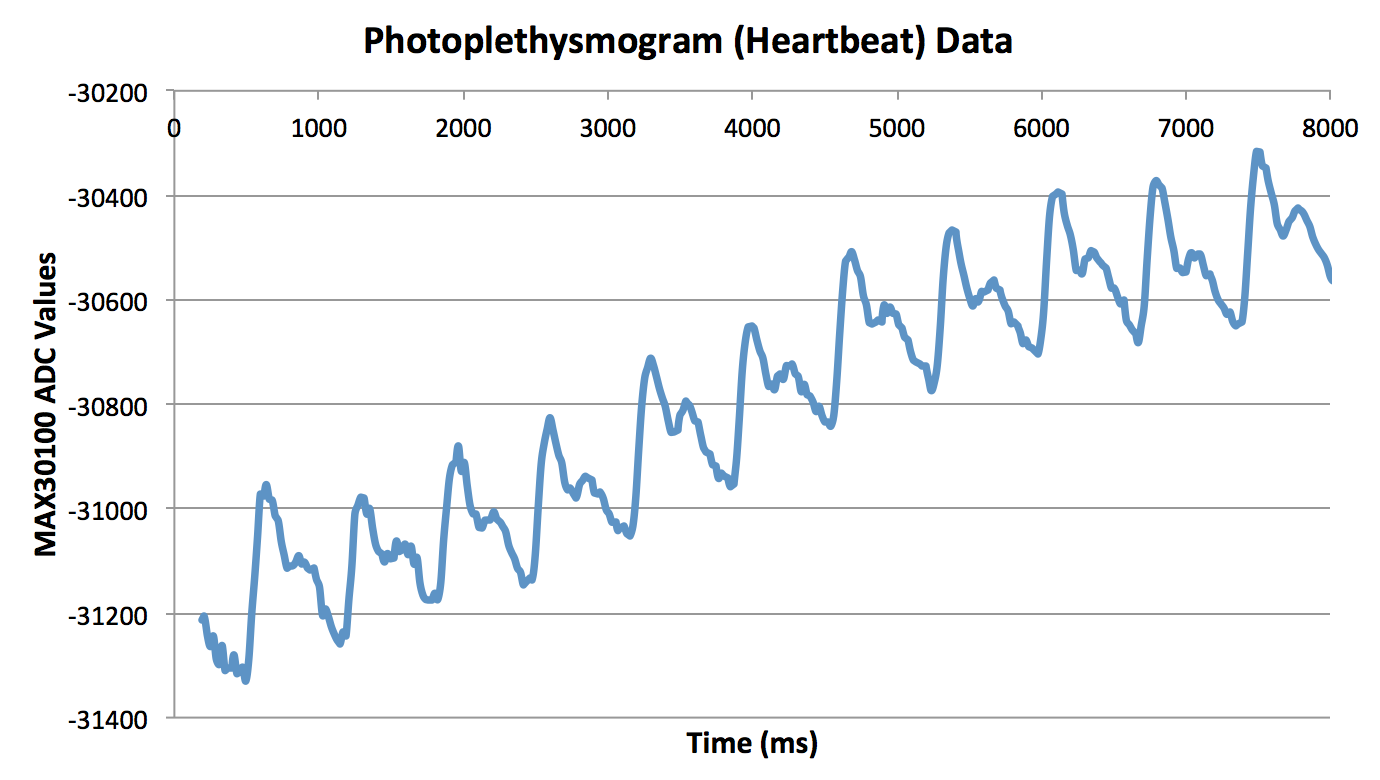
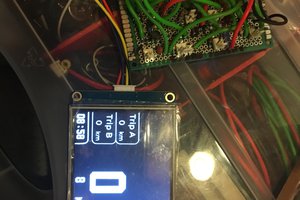
A number of users have developed a library for the MAX3010X family of chips. I was hoping to use the MAX30101 because of the green light capabilities. I could not get the MAX30101 functioning correctly on my shield before contest end date. However, I do have some data from when I was playing with a MAX30100 breakout a few months ago. The MAX30100 and MAX30101 are basically identical chips. I'll show you my data with the MAX30100. The first big peak you see shows the sudden increase in blood volume in my fingers due to my heart pumping (ventricles contracting). The second peak indicates the closure of the aortic valve in my heart.
Pulse Oximeter with the MAX30101
Pulse oximetry is a technique used to measure our how much oxygen is dissolved in our blood or, blood oxygen saturation. In order to do so, we will use photoplethysmography as we did for calculating heart rate. Pulse oximetry is a little more involved than simply calculating heart rate and requires quite a bit of processing and clinical validation to get a legitimate metric. However, we can get a decent estimation with a few DIY tricks. I am still implementing pulse oximetry on my board at the moment. For now, I'll link you to the guide I'll be following. Raivis Strogonovs has done a good job documenting his journey on his blog.
Electrocardiogram, Electromyogram, and Electrooculogram with our Super Simple EXG Circuit
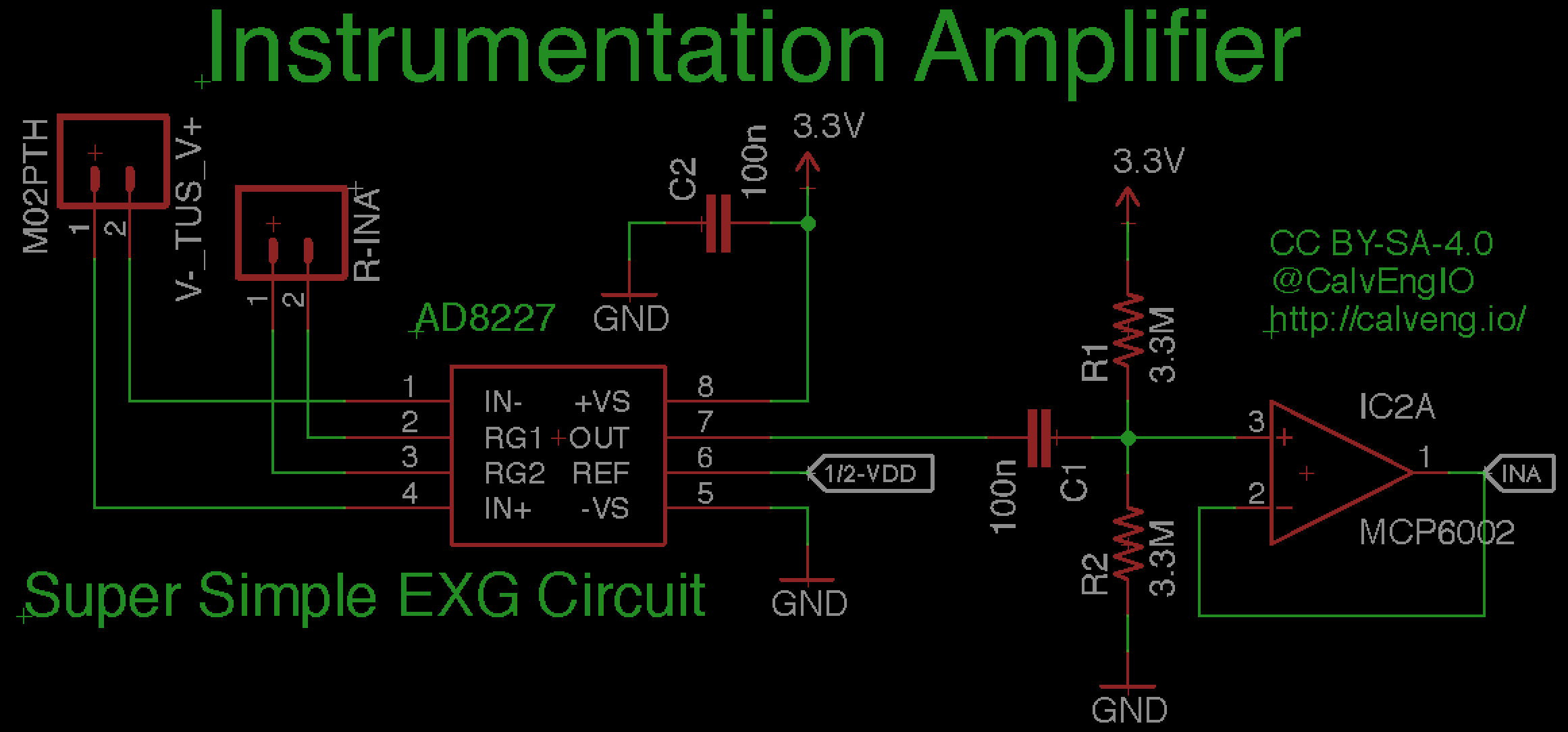
Biopotential measurements are a class of measurements that deal with measuring bioelectric signals that our bodies naturally produce when doing certain functions. There are a few popular ones such as the electrocardiogram and electromyogram that have been pretty popular in the maker culture. Each of these measurements can be accomplished using a pretty simple circuit. Of course, more complex implementations of this circuit exist that give you a lot more information. But, I'll keep it simple for brevity sake. For the Biomed Shield, I'll use a simple instrumentation amplifier circuit. An instrumentation amplifier allows us to interface to our body's electrical signals similarly to how we use a multimeter to measure voltage. The multimeter has a very high impedance so we don't "load" the circuit we're measuring. Our instrumentation amplifier does the same thing when measuring biopotential signals.
The next few figures demonstrate a few signals captured with the Arduino 101 from the Biomed Shield. The first figure is of the electrocardiogram, which document the electrical signals of the heart during operation. The second is the electromyogram, which...
Read more »

 Lithium ION
 Minimum Effective Dose
Great project!