 Orlando Hoilett
Heart Rate Monitoring with the MAX30101
Heart rate is a measure of how many times our heart beats per minute and is usually represented in just that "beats per minute" or BPM. Photoplethysmography is a very popular technique for measuring heart rate. Photoplethysmography takes two popular forms, reflectance photoplethysmography and transmission photoplethysmogrpahy. In transmission photoplethysmography, a light shines through an extremity such as a finger and a detector measures the amount of light that passes through. When the heart pumps blood through the body, we notice a momentary increase in blood volume in the fingers. As a result, the amount of light that passes through the finger changes with this changing blood volume and is detected by the photodetector. In transmission photoplethysmography, instead of measuring the amount of light that passes through the finger, we measure the amount of light that reflects off the finger. The MAX30101 by Maxim Integrated is in a specialized integrated circuit that is able to perform reflectance photoplethysmography. The MAX30101 contains three light-emitting diodes, one red, one infrared, and one green. The IC also contains a photodetector and contains all the circuitry necessary to process the recorded signal in order to detect heart beats and subsequently, calculate heart rate. By using this specialized IC, we can detect heartbeats and subsequently, calculate heart rate.
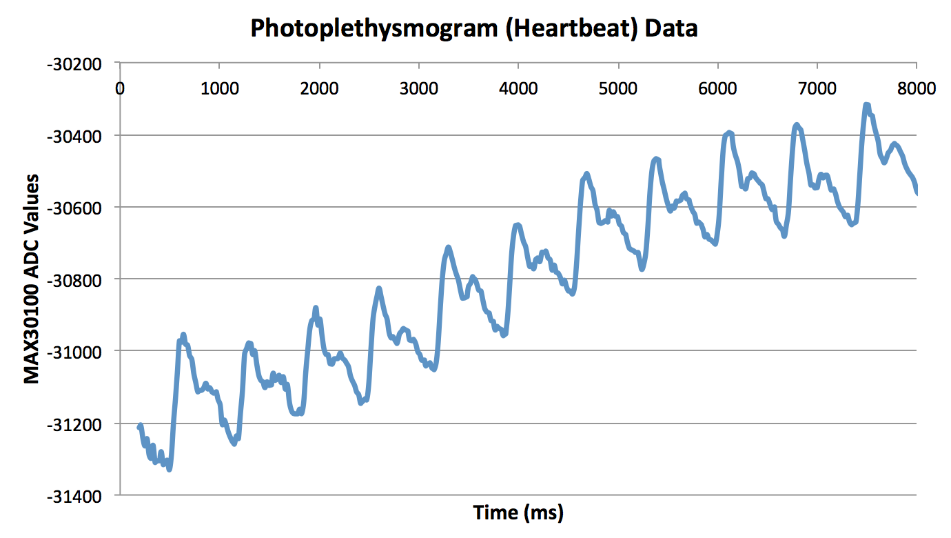
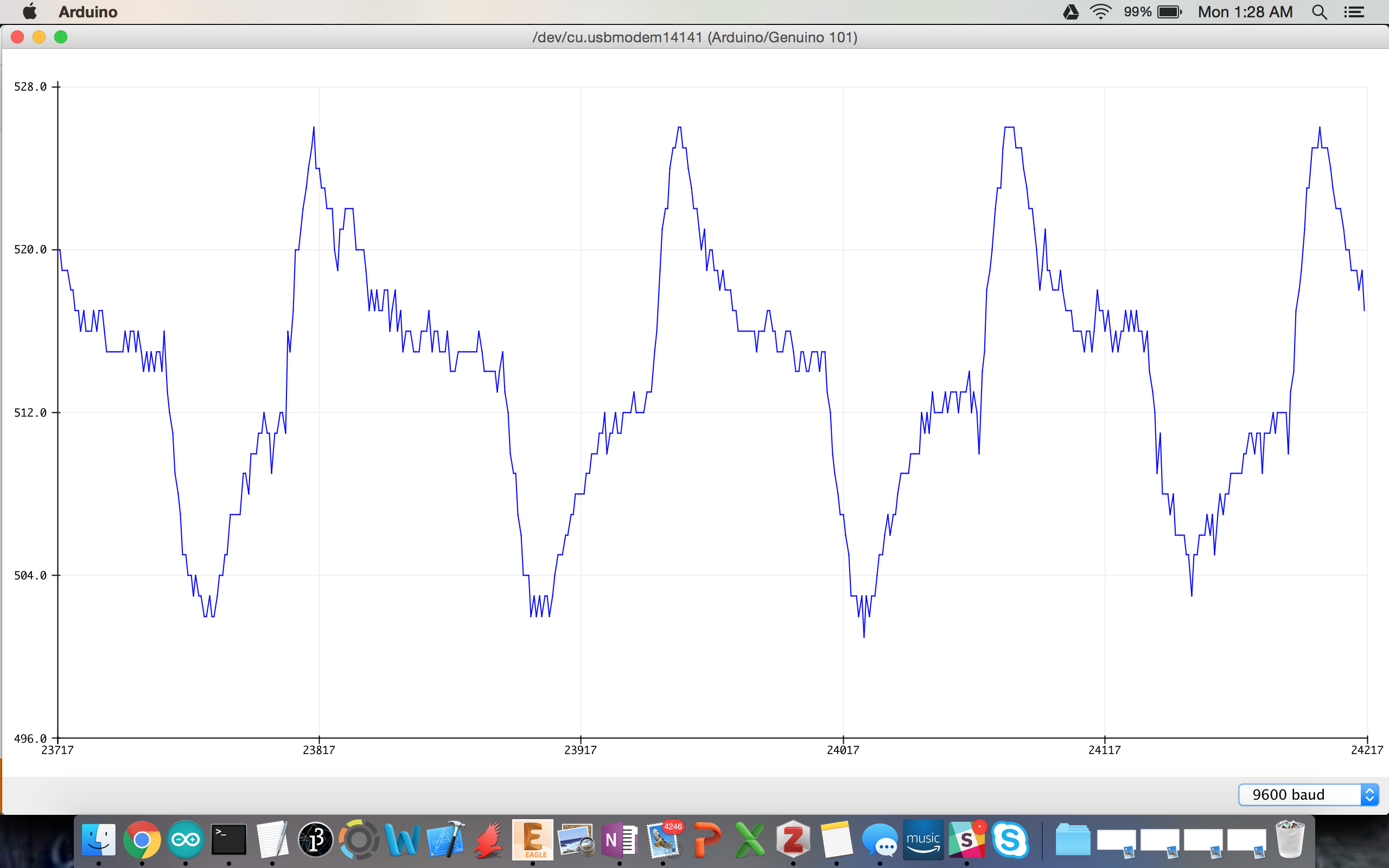
A number of users have developed a library for the MAX3010X family of chips. I was hoping to use the MAX30101 because of the green light capabilities. I could not get the MAX30101 functioning correctly on my shield before contest end date. However, I do have some data from when I was playing with a MAX30100 breakout a few months ago. The MAX30100 and MAX30101 are basically identical chips. I'll show you my data with the MAX30100. The first big peak you see shows the sudden increase in blood volume in my fingers due to my heart pumping (ventricles contracting). The second peak indicates the closure of the aortic valve in my heart.
Pulse Oximeter with the MAX30101
Pulse oximetry is a technique used to measure our how much oxygen is dissolved in our blood or, blood oxygen saturation. In order to do so, we will use photoplethysmography as we did for calculating heart rate. Pulse oximetry is a little more involved than simply calculating heart rate and requires quite a bit of processing and clinical validation to get a legitimate metric. However, we can get a decent estimation with a few DIY tricks. I am still implementing pulse oximetry on my board at the moment. For now, I'll link you to the guide I'll be following. Raivis Strogonovs has done a good job documenting his journey on his blog.
Electrocardiogram, Electromyogram, and Electrooculogram with our Super Simple EXG Circuit
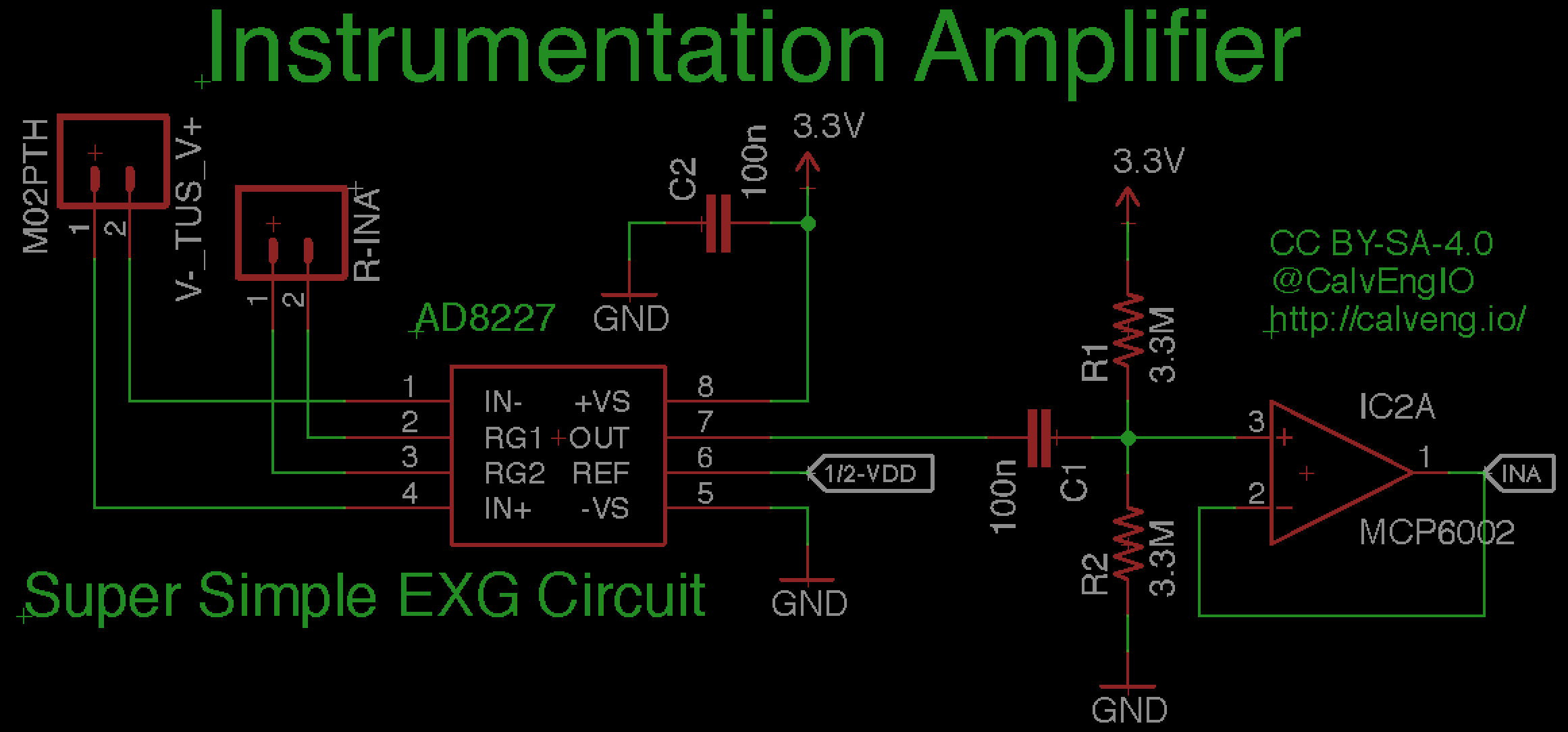
Biopotential measurements are a class of measurements that deal with measuring bioelectric signals that our bodies naturally produce when doing certain functions. There are a few popular ones such as the electrocardiogram and electromyogram that have been pretty popular in the maker culture. Each of these measurements can be accomplished using a pretty simple circuit. Of course, more complex implementations of this circuit exist that give you a lot more information. But, I'll keep it simple for brevity sake. For the Biomed Shield, I'll use a simple instrumentation amplifier circuit. An instrumentation amplifier allows us to interface to our body's electrical signals similarly to how we use a multimeter to measure voltage. The multimeter has a very high impedance so we don't "load" the circuit we're measuring. Our instrumentation amplifier does the same thing when measuring biopotential signals.
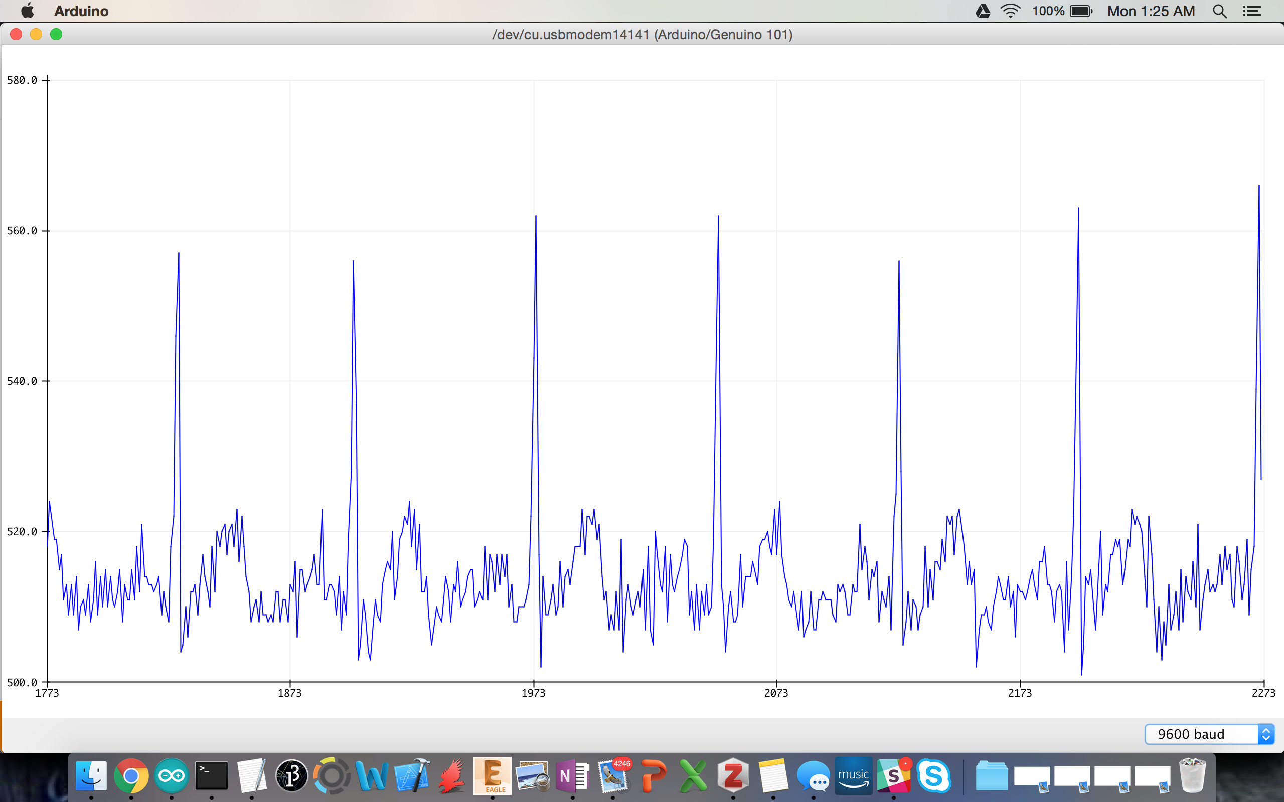
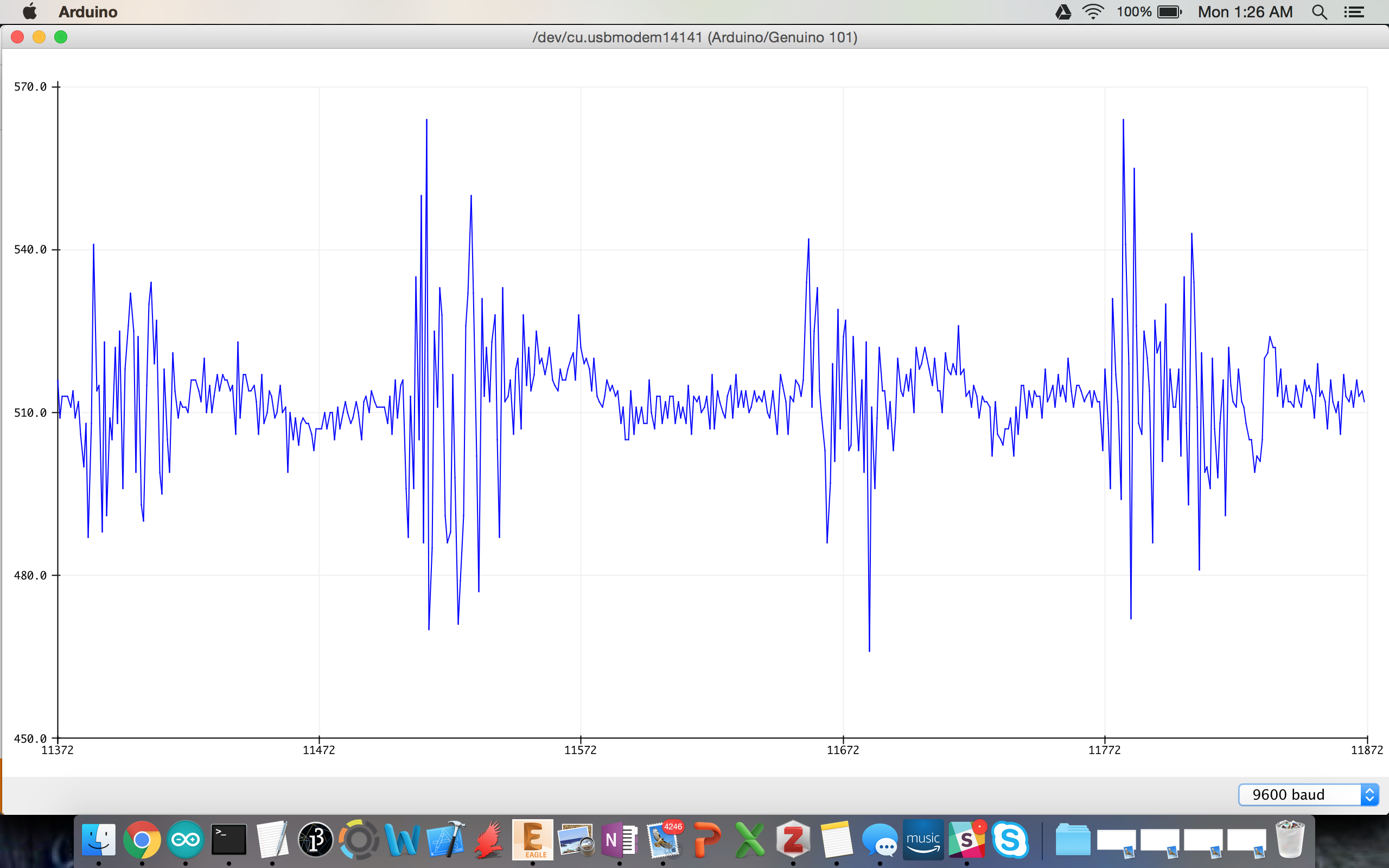
The next few figures demonstrate a few signals captured with the Arduino 101 from the Biomed Shield. The first figure is of the electrocardiogram, which document the electrical signals of the heart during operation. The second is the electromyogram, which is the electrical signals that cause my muscles to contract. The third is the electrooculogram which is measuring the electrical signals produced when moving my eyes side-to-side
Bioimpedance with the AD5934
Bioimpedace is can be another class of bioelectrical measurements. For bioimpedance, however, we are measuring the impedance (or resistance, to keep it simple) of the body instead of measuring the electrical signals produced by the body. Bioimpedance analysis is useful for a number of things like calculating body fat or analyzing sympathetic nervous response. I am still working out some bugs in the Biomed Shield's bioimpedance circuit. In the meantime, I'll direct you to a few Instructables written by former students of mine in which they used bioimpedance to analyze body fat contact and also chest resistance.
https://www.instructables.com/id/Body-Composition-using-BIA/
https://www.instructables.com/id/Body-Composition-Analyzer/
https://www.instructables.com/id/Thoracic-Impedance/step9/Electrode-Placement/
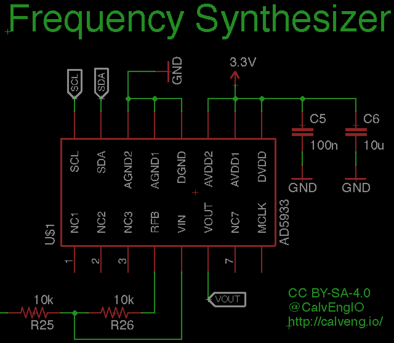
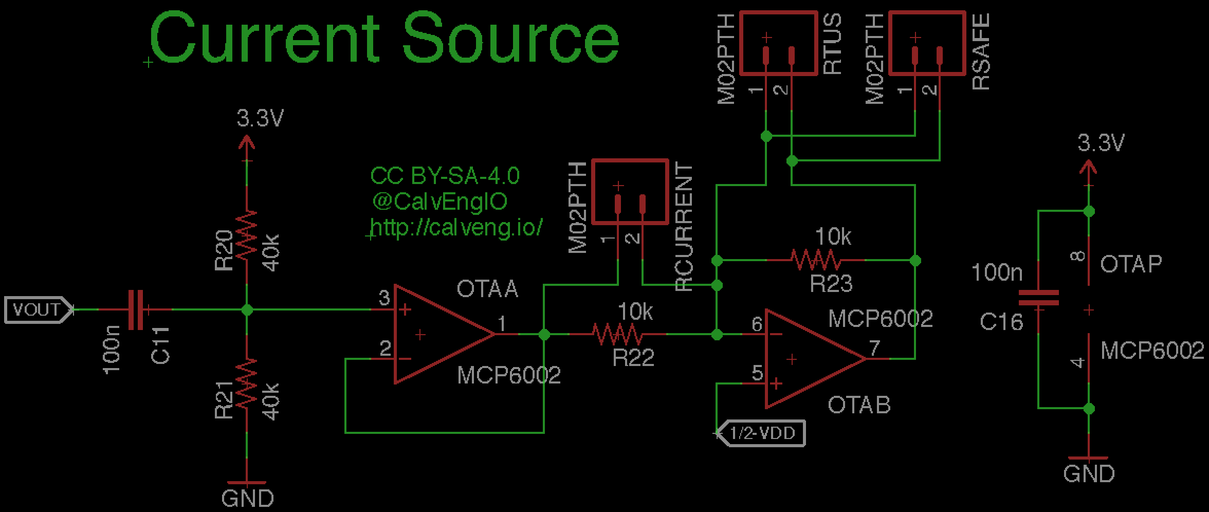
However, I'll give a bit of a description regarding the bioimpedance circuit. The circuit uses the AD5934 impedance analyzer which is a really fancy chip for measuring impedance (or resistance, to keep it simple) of different targets. In our case, we want to measure the resistance of a biological system. In my circuit the output of the AD5934, labeled "VOUT" is first high-passed filtered and centered around 1.65V (one half the supply voltage) and then sent into a buffer amplifier (OTAA). OTAB is the current to voltage converter. RTUS, is the "Tissue Under Study", or whatever biological material is being measured. You can connect to RTUS through the pin headers installed on the shield. I'll probably change these pin headers to a TRRS jack in a future iteration of the shield. It might look a little more visually appealing. For example, you can connect the RTUS across your arm to calculate the fat/water composition in your arm.
Be very careful with the bioimpedance circuit. In this circuit, you are injecting a small current into your body. Currents low as 1 milliAmperes can cause a tingling sensation. The bioimpedance circuit is specifically designed to allow no more than 100 microAmperes of current. Use the circuit at your own risk.
Body Temperature with the MLX90614
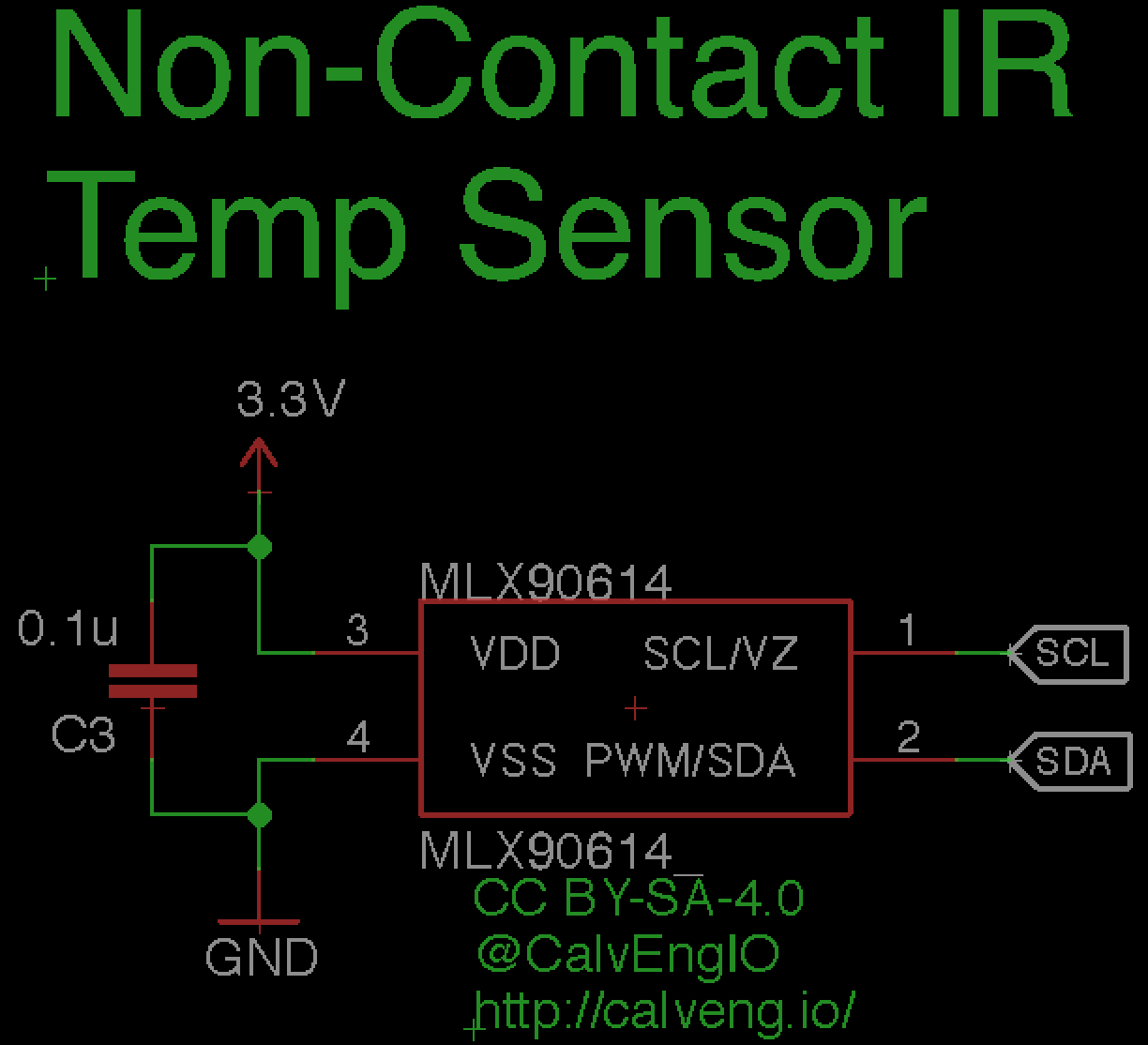
Body temperature is useful for general wellness. We often use body temperature to diagnose fevers and other ailments. The MLX90614 is a convenient way to measure body temperature because it is non-contact. It's a pretty popular hobbyist component. For proper core body temperature (temperature inside your body), without actually sticking a temperature sensor inside our bodies, we would need to take a rectal temperature. Yes...you read that right. Since I will not be sticking my Arduino 101 in my rear, I'll just take a few readings as I move my hand away and towards the sensor. (As I'm writing this, it's really late, and I'm really lazy so I apologize for the un-scientific tests). The Arduino will communicate with the MLX90614 using I2C. Adafruit has written a pretty nice library for the MLX90614. We'll borrow from them and use a simple example sketch found in the "examples" folder to get some data. You should see the temperature increase from 69 degF to 90 degF. That happens when I move my hand closer to sensor. The temp goes back down to about 71 degF as I move my hand away from the sensor.
Ambient Light with a CdS Photocell
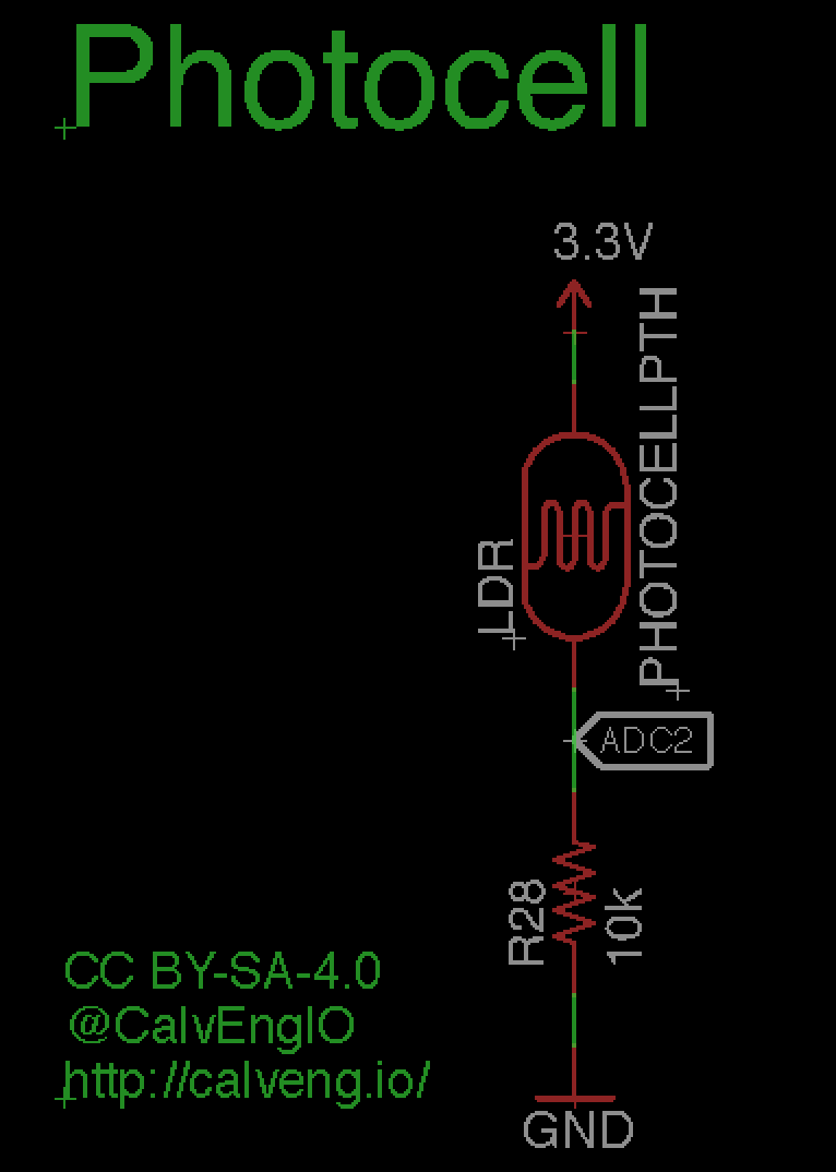
Sunlight is surprisingly important for general health and well-being. It may not be as critical as some other metrics, but extended periods without sunlight have been shown to have detrimental effects according to some research (source). Furthermore, too much sunlight has negative effects as well, resulting in sunburn as most people are probably already familiar. To characterize ambient light, I included a photocell on the shield. A photocell is a pretty simple component that changes resistance with changing light. We will interface the photocell with a voltage divider and read the change in voltage to observe changes in ambient light. Admittedly, to truly characterize sunlight intensity to prevent against sunburns, it would make more sense to use an ultraviolet (UV) sensor instead. UV rays are the portions of sunlight that give us sunburn. I will add a UV sensor in my future iteration of the Biomed Shield.
Ambient Temperature with a Thermistor
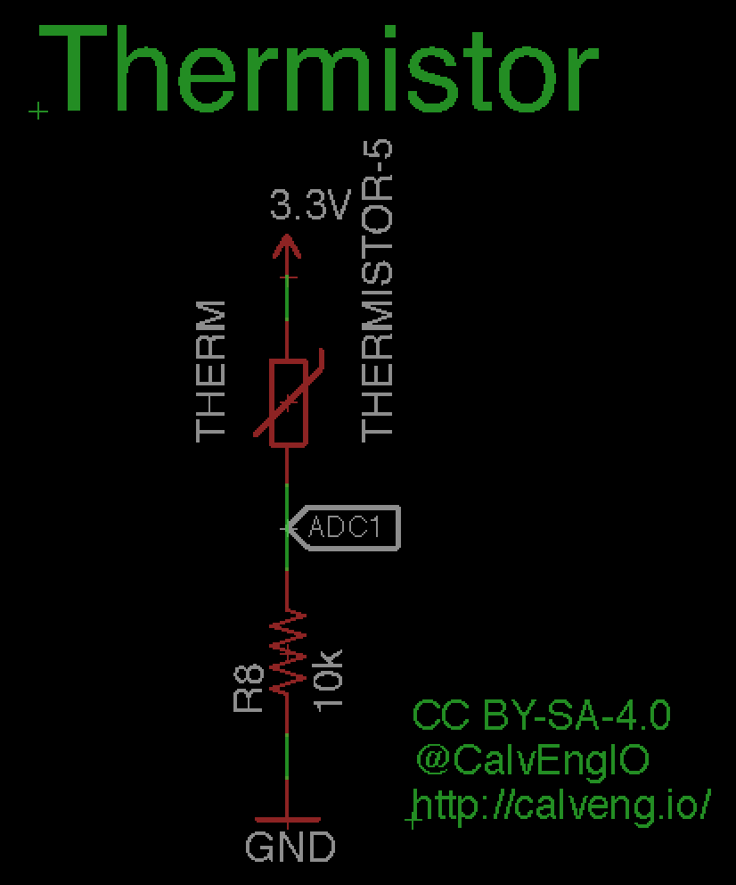
I included an ambient temperature sensor for general temperature measurement applications. Weather patterns have shown to affect general well-being (source). For some people, sudden changes in weather patterns can trigger colds, arthritis flares, etc (source). On a less serious/scientific note, no one likes it too hot or too cold, so use this sensor to assess comfort levels. Thermistors are perfect for ambient temperature sensing because they are cheap and very easy to interface with a microcontroller. For our temperature sensing circuit, we configure the thermistor in a voltage divider circuit. Following a very simple equation Figure x, we can easily calculate temperature. I will include a humidity sensor in my future iteration of the Biomed Shield.
I tested the sensor by simply measuring ambient temperature in my living room with and without obstructing touching the thermistor with my fingers. My thermostat was set to about 18 degrees C (65 degrees F), but I had my living room lamp on which usually bumps the temperature up a few degrees. The sensor read about 24.4 degrees C, which seems a bit high. It's probably 2 or 3 degrees off, which is normal for these types of sensors. You can choose to either calibrate the sensor properly or subtracting the offset. However, this is fine for my purposes. The output of the sensor increases when I touch it, which is expected. Rubbing the sensor with my fingers will create a little friction, increasing the temperature a bit.