Pi0CKET - Clicker
To get the true Pi zero experience in your pocket, we are gonna need some buttons!!
To get the true Pi zero experience in your pocket, we are gonna need some buttons!!
To make the experience fit your profile, pick a username and tell us what interests you.
We found and based on your interests.
So this is an old old project, but the idea still stands!! I have been playing with ideas of making it bigger and adding more power (im looking at you cm4!!) but it wouldnt really add a massive level of value for the project as a whole
My ideas for power management could do with a bit of a tweak (the vampire drain of a single unlit WS2812 is shocking) and a nice case with some proper buttons would go a long way to making this a useable device...
Its been a while!! My idea to move to using an atmega328 was a good one, however my idea to try and use the chips internal clock was not!! In order to flash the atmega with the bootloader that determines internal clock usage, we will need to attach the chip to an exteran clock source!! I also found all in one resonators that have the xtal and caps in the one tiny package. This results in a pretty standard arduino pro mini format, which makes bootloader and code flashing super easy and super standard.
After many months of not having time to touch the new boards, I finally got to soldering it up, and BEHOLD!!!!!!!!
A while back, i contacted a company in china to manufacture a custom snapdome sheet to make things much easier for the project. After a few weeks and a small fee, i got some sample sheets
they worked out great, however the minimum order qty is going to be a killer!! The clear layer means that the silkscreen text can be shown through it, making life easier when typing. I just need to work on the key layout, and add in some 'layers' to allow more character input than the current number of keys allows
Onwards!!!!!!
So after many attempts to get the attiny88 to play ball, I think it's time to move on and use the chip I should have used all along!
Behold the power of the atmega328 and it's well trodden paths!
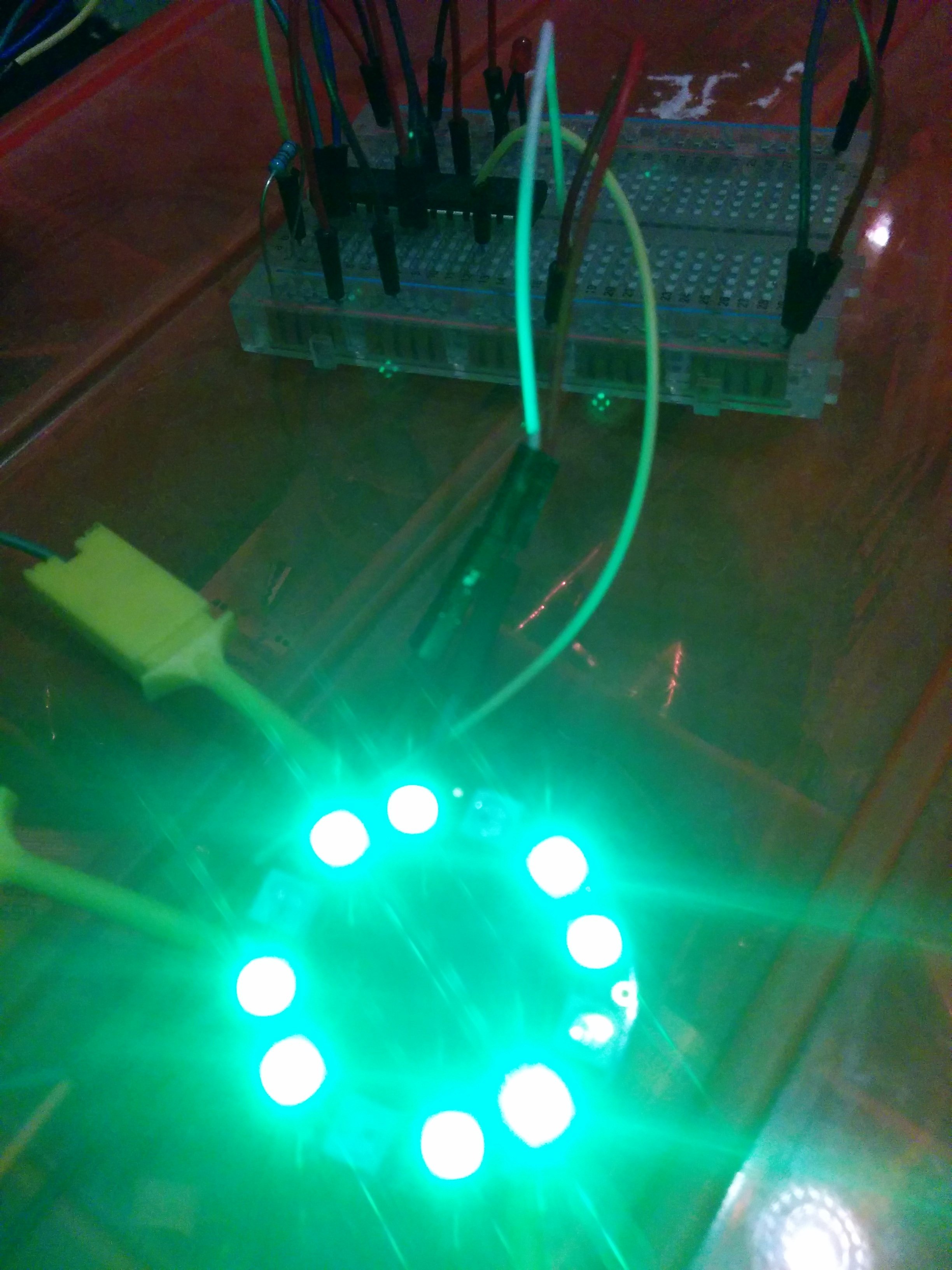
Apologies for the very shoddy camera work but it's running the neopixel's on its internal clock
Now I had decided that I wanted to keep to my path of keeping things super simple, so I have gone for the internal clock, thus saving myself an additional 3 components. I have also borrowed some elements from the Arduino Pro mini schematic so I can be sure that I'm doing it right!
Currently going through the old board carefully ripping up traces and adding new ones, trying to squeeze in the extra ftdi header needed for code upload duties.
Revision 3.0 is imminent...
So my upgrade from attiny85 to attiny88 wasnt as smooth as first planned. My first issue was having non tented vias under a gnd pad on the chip. I tried some kapton tape, which was too thick, then various paints, but realised that the soldermask should be thick enough to stop the pad touching anything, and it turns out i was right!!
So once its all soldered on, and i bodge myself an ISP programmer together, i started testing my code. The first issue i had, my neopixel wouldnt work. So my first thought was that i had melted it during my various reflow attempts, but some external testing proved it still lived. Some more testing to prove that im using the correct pin (PA3/PCINT27/arduino 26) so i cracked open the trusty blink code, and sure enough that pin is correct, and i also know my solder joints are ok too!! So it seems that the attiny88 doesnt have the minerals to run my neopixel :(
The joys of microprocessors eh!!
So once i got the keyboard working, i had a little play with the attiny85. My basic code would use some internal reference trickery to get the internal voltage, then reporting back over i2c. The problem being, an attiny85 doesnt actually have proper i2c support, and so it was flakey to say the least!!
So after some searching, I found that the attiny88 has better i2c support, and more pins too, meaning that i can use a proper interrupt for the on/off button too. as a third and final bonus, it is also a few pence cheaper!!! it pays to look around eh!!
Some other changes see the power button being swapped for a 90 degree one to sit top centre on the board, and the neopixel has been moved to the back to save the eyes. It will work better too, filling the area between the pcb and the pi, with a glow of light. or maybe it could be used to illuminate a power switch later
there was of course a few fixes to the original design to correct my wildly inaccurate guesses on the keyboard chip, simply adding some more pullups, and i think we are good to go....
how many times can i check before i press the go button?
So after fixing some bad solder job (hand soldered qfn24 only half worked), and then fixing some bad circuit design with the help of @mozzwald , and getting the kernel rebuilt with the driver and overlay (credit again to @mozzwald ) we now have a working keyboard. I seem to have got my map reversed, but that's a simple fix 😀
Apologies for the vertical video 🙈 I was too excited to notice.
Time to design a case me thinks....
I was a little apprehensive about hand soldering the QFN24 chip for the keyboard, looking at it, the thing was crazy small! I forget how small things are after spending many hours with stuff zoomed a few hundred percent on the computer screen
(dont look too hard, my keyboard needs cleaning)
so i took the plunge
tinned the pads with a small amount of solder, applied a later of flux, clamped the chip with some tweezers and a clothes peg (nothing like having the right tools) and gave it some love with the iron
finding the limits of my phone camera, and it looks better in person.
much soldering later and we have filled the pads
I burnt some code onto the attiny85, grabbed the nearest sd card with ili9341 running, added a battery and pressed the button
looking good!!
There are of course issues, my idea of using a clip on programmer is fine for the attiny85, but when the pi covers the chip, you can no longer program it!! need to add a ICSP header. Im also struggling slightly to get my attiny to behave as i want. Getting it to respond over i2c kills my sleep code, think i have some conflicting interrupts...
to be continued......
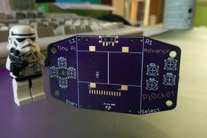
Some sexy board goodness arrived today
I need to get moving on sourcing some components! 😀
so building on my last idea, little bit of shuffling and everything is now connected (hopefully) and in the right place (also hopefully)
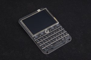
its looking pretty good, the front has the buttons, screen, and a neopixel
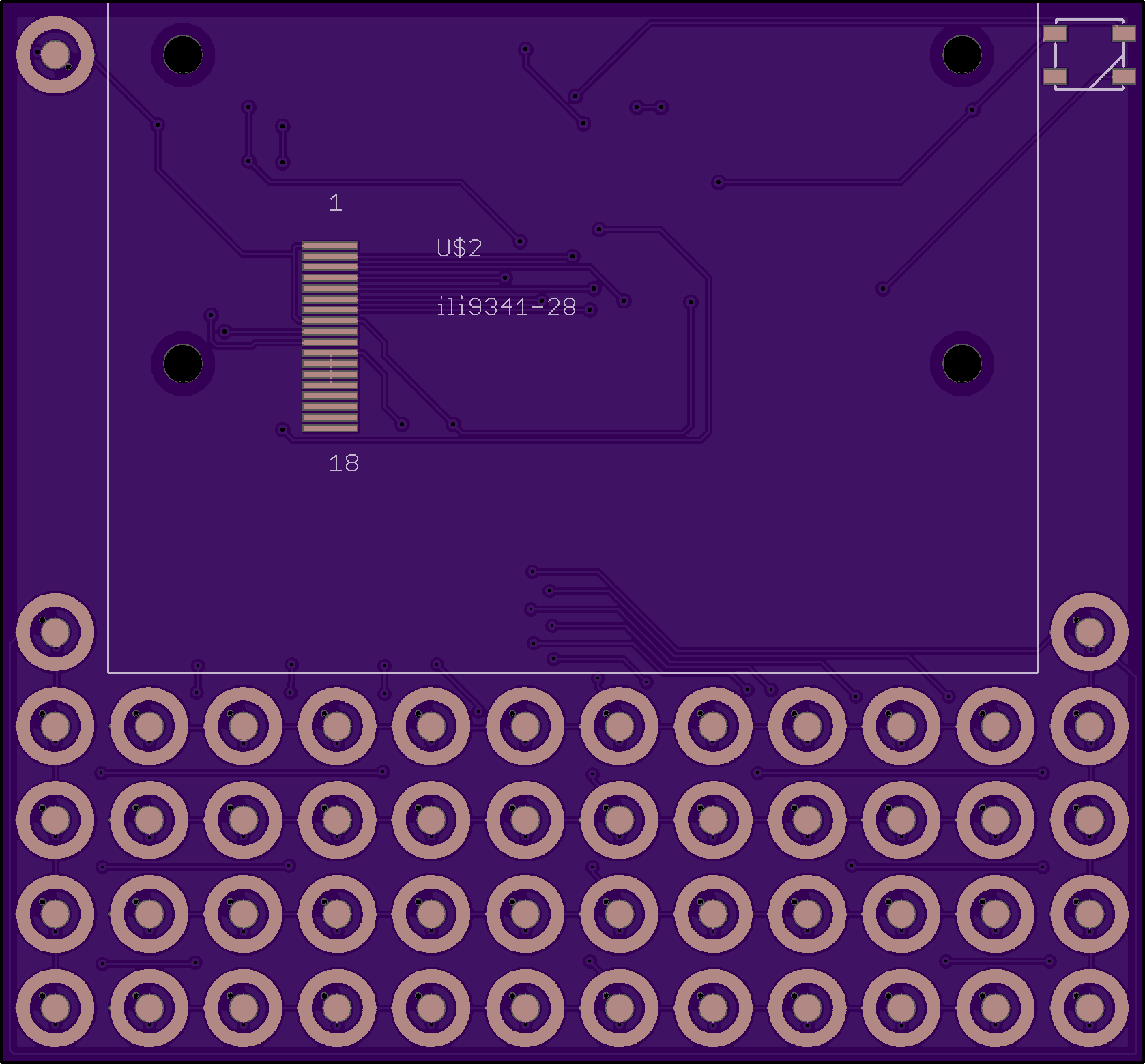
and the back has a nice juicy space to place a big li-po (3000mah should yield 10 hours) and all the other components are hidden beneath the pi on its smd header.
a little bit more checking and we might be there!
So i got everything as i wanted it, then i thought 'oh wouldnt it be great if we had access to gpio'. so after much shuffling i found that i didnt really have the space (was thinking of using the space each side of the screen) and was tempted to just leave it. While doing other things i had a brainwave that i could use a hotplate to sink gpio headers into the pi (crazy thinking). then the lightbulb came on, and i thought 'why not use smd headers!!' this would then mean that its nice and easy to solder the pi on, and it also adds the advantage of being able to use hats (could even pop a pi3 on there with minimal effort!!)
So then things move on from there, and i had the idea of moving all the components under the pi, so the bare bit of board behind the keyboard can have a nice hunk of battery attached to it with no components getting in the way. Some messing about and it might work!!
back to the routing!!
Create an account to leave a comment. Already have an account? Log In.
How long this device work, for example is possible compiling kernel?
it could do, its got a 2000 mah battery, and the zero uses about 300-400ma. so it could last 5 hours. there would of course be the option to charge it while it is on
How increasing this to a week?
steping down cpu Hz, memory, meybe turn off switch wifi etc.
I know I'm late... but can I buy a PCB, fully assembled? I'm in the US, PM/Chat me for address info :) I have a Pi Zero :)
hi there
i never got round to selling these, but im working on a better version, should be available soonish
This project fills the need/desires of folks who have/used a #PocketCHiP now that NextThing.co is bankrupt. The custom snapdome sheet would be practically be necessary if used daily (I'd order several so I could have replacements after wearing them out.)
What would be a great board alteration is to add holes for a lanyard clip and some "prop up" holes for a pen/pencil like the PocketCHiP had. Both would make extremely helpful to sit upright on a desk/table/workbench to observe or grab it. The lanyard clip hole would be awesome so it could be worn it at conferences as badge (also around the office or workshops).
Speaking of #badgelife, if you add the lanyard hole, consider providing additional traces of the I2C for a proper SOA connector -- which is pretty much a requirement for #badgelife.
Cheers
it even has the blinking LED too!! I have had a custom snapdome sheet prototype made and it is much better, the only issue being the rather large minimum order of 2000 from the supplier making it rather expensive.
you can see the snapdome sheet on here
https://www.instagram.com/p/Bn83kKIlKph/
I've been looking around for limit-run "kickstarter" like project where layered PCBs were bolted together to form a "tablet". It was a microcontroller with BASIC, a proto area and 1/4 VGA screen. The keyboard was formed by the space/well where the lower traces were styled to receive a keypress from an upper layer stiff mylar-like sheet - the "key contacts" were on printed on the under of the mylar and was cut to form a "U" shape so they could be pressed down into the key-well. It was really cool.
But while trying to find it, I found this PDF on CapSense:
http://www.cypress.com/file/41076/download
I've an Adafruit Arduino shield that's a capacitive keypad - it only requires the exposed PCB traces. With some inspiration from CapSense PDF's page 10 & 11, you might need to put non-moving spacers as "keycaps" to reduce the sensitivity or "keybounce" effect. Maybe spacers that have capacitance at one level but changes when physically compressed.
Plus the spacers might be able to have the lettering printed on them without impacting functionality. I've seen tons of examples of capacitive touch keys/buttons using arduino. Remember, this is more like a thumb-board. Folks will not be touch typing on it. It just needs some like prevention so folks are not dragging other fingers or their palm (at the Thumb's base) across the keyboard traces.
Another source of inspiration may come from http://rapidkeypads.com/
(Update. James, apparently I'm not being displayed a 'reply' option to your comment unlike the rest. That's it. thank you very much. It provided thought of how such a thing could be created with a Pi Zero.
At the same time, I think the Clicker would likely be more affordable having less PCBs involved.)
Markstinson, you seem to be describing this project: https://hackaday.io/project/9692-ello-2m
If you decide to offer those snapdome sheets as a separate product that might well be popular on Tindie or wherever :)
i need AltGr for polish chars ąźł ćśń etc.
i need pgUP/Down Home,end for terminal
is possible to add solar panel? how many hours working this device?
alt-gr is there to the right of the space buttons. I tried to keep that pretty standard
i was thinking of using the Planck style 'layers' similar to the function layer you get on laptops, but with 2 function layers. These could all be customisable, but one layer could take the standard left/right arrow keys and make them home/end, then it could also take up/down on the arrow keys and make them pgup/pgdn
battery life depends on the battery size, but you should get about 10 hours from a 3000mah cell. You could add solar charging. if it outputs more than 300mah, then it could in theory run the device, but you would need the battery to act as a buffer if the sun goes in
I hate function keys
imagine ctrl+alt+function+arrow right to change terminal? Sorry not usefull, but second or third function (or language) is very usefull
fn2+arrow left is aceptable, but pgupdown home end must be normal because i use terminal and text editor.
jump for end document is ctrl+end
ctrl+Fn1+....etc no thanks
solar charger build in similar in solar calculators
yeah, there are always going to be compromises on something like this. It is a tiny footprint ( 3.36 x 3.12 inches or 85.2 x 79.2 mm) so you are never going to get a full 104 key keyboard on there
This is great! To be honest, I'll be interested in copying your project at some point =)
Thanks!! feel free to borrow bits. im technically doing nothing new here.
I do plan on trying to make a few once i have the kinks ironed out. Try and make it as cheap as possible :)
I had this idea of taking N900 keyboard plastic keys available from eBay as a replacement parts and building a case+PCB for it - maybe I'll go with it sometime this year =)
sounds good!! if you can get your hands on the sticker sheet with the domes that was made for the n900 you could mod to board to suit!!
Yeah I'm not the first, trying to get something small and skinny
Oh, this project looks familiar and I like it, looking forward to see the result.
---shameless plug warning---
I see you are solving some of problems I solved too for my portable computing projects, like https://hackaday.io/project/19437-raspberry-pi-zero-handheld-computer or https://hackaday.io/project/643-minibsd-laptop-computer or perhaps https://hackaday.io/project/3511-pavapro-portable-avr-programmer
how did i never reply to this?
these look good. i will have a good look at these
Become a member to follow this project and never miss any updates
 T. B. Trzepacz
 deʃhipu
 arturo182
 moosepr
can i have the gerber file pls