 oblu.io
A SHORT INTRODUCTION
The project is about making the robot move in a pre-defined path with precision, without making use of GPS or WiFi or Bluetooth for positioning, not even map or building layout plan. And draw its actual path (to the scale), in real-time. The bluetooth can be used as a substitute of wire, for transmitting real-time location information.
THE INTERESTING BACKGROUND STORY
Our team's prime agenda is to develop shoe-mounted pedestrian navigation sensors. However, we were approached by an academic research group with the requirement of navigating robot indoor and simultaneous monitoring its realtime position. They wanted to use such system for mapping radiation in an enclosed chamber or detected gas leakage in an industrial setup. Such places are hazardous to human beings. looking for a robust solution for indoor navigation of our Arduino based robot.
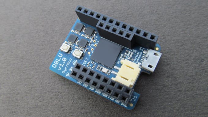
Our obvious choice for any motion sensor module (IMU) was "oblu" (Ref above image). But the tricky part here was that oblu's existing firmware was suitable for foot-mounted indoor Pedestrian Dead Reckoning (PDR ) or Pedestrian Navigation, in simple words. Oblu's PDR performance in indoor as a foot-mounted IMU is quite impressive. Availability of Android app (Xoblu) for oblu's real-time tracking as shoe-sensor, adds to the advantage. However, the challenge was to make use of its existing algorithm which is based on human walking model, for navigating robot and monitoring it.

A brief intro to "oblu" - "oblu" is a miniaturized, low cost and opensource development platform targeted towards wearable motion sensing applications. It is Li-ion rechargeable battery operable and allows onboard USB battery charging. It has an onboard Bluetooth (BLE 4.1) module for wireless communication. "oblu" hosts a 32-bits floating point microcontroller (Atmel's AT32UC3C) which allows solving complex navigation equations onboard. Therefore one perform all the motion processing on oblu itself and transmits just the final outcome. This makes integration of oblu with the associate system extremely simple. "oblu" also hosts multi-IMU (MIMU) array which allows sensor fusion and enhances motion sensing performance. MIMU approach adds to the uniqueness of "oblu".
Oblu's internal computations are based on human walking. Oblu gives out displacement between two successive steps and change in heading. How - when the foot comes in touch with the ground, speed of the sole is zero, i.e. the sole is at standstill. <Refer above video.> This way Oblu detects 'steps' and corrects some internal errors. And this frequent correction of errors, results in great tracking performance. So here lies the catch. What if our robot also walks in the same fashion - move, stop, move, stop..
Infact, oblu could be used for any object whose movement has regular zero and nonzero moments.
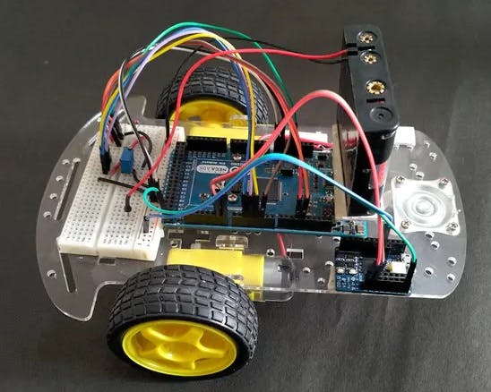
Thus we moved ahead with oblu and in no time we could assemble our robot and the tracking system. Rest of the story is in the following video...
SYSTEM DESCRIPTION
The robot moves in a pre-programmed path and transmits (over bluetooth) its actual movement information to a phone for real-time tracking.
Arduino is pre-programmed with path and oblu is used for sensing robot's motion. oblu transmits movement information to Arduino at regular interval. Based on that, Arduino controls wheels' movements to let robot follow the predefined path.
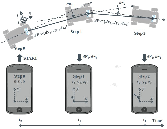
The robot's path is programmed as a set of straight line segments. Each line segment is defined by its length and orientation with respect to the previous one. The robot's motion is kept discreet, i.e. it moves in straight line, but in smaller segments (lets call 'strides' for simplicity). At the end of every stride, oblu transmits stride length and extent of deviation (change in orientation) from straight line, to Arduino. Arduino corrects the alignment of robot at every step on receiving such information, if it finds deviation from the pre-defined straight line.
As per program, the robot is always supposed to move in a straight line. However, it may deviate from straight line and may walk at a certain angle or skewed path because of non-idealities like uneven surface, mass imbalance in robot assembly, architectural or electrical imbalance in dc motors or the random orientation of front free running wheel. Take one step.. correct your heading... move forward. The robot also moves backwards if it travels more than the programmed length of that particular line segment..
The next stride length depends upon the remaining distance to be covered of that particular straight line segment. The robot takes large strides when the distance to be traveled is larger and takes smaller strides close to destination (i.e. end of every straight line segment).
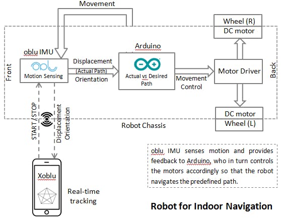
IMU Oblu transmits data to Arduino and phone (over bluetooth) simultaneously. Xoblu (the Android app) performs some simple computation to construct the path based on the movement information received from the robot, which is used for real-time tracking on phone. (Path construction using Xoblu is illustrated below.)
In summary, oblu senses motion and communicates movement information to Arduino and phone at regular intervals. Based on the programmed path and the motion information (sent by oblu), Arduino controls the wheels' movements. The robot's movement is NOT remotely controlled except for start/stop commands.
PATH MODELLING
The robot could be best controlled if it walks in straight line segments only. Therefore, the path must be first modeled as a set of straight line segments. Below pictures contain couple of example paths and their representations in terms of displacement and orientation. This is how the path is programmed in Arduino.

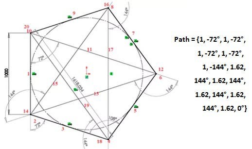
Likewise any path which is a set of straight line segments, can be defined and programmed in Arduino.
CIRCUIT ASSEMBLY
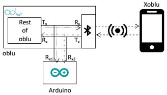
Below is the top level system integration diagram. Arduino and oblu are part of the hardware assembly. UART is used for communication between Arduino and oblu. (Please note the connection Rx/Tx connection.) Direction of dataflow is for reference only. The whole hardware assembly communicates with smartphone (Xoblu) using bluetooth.
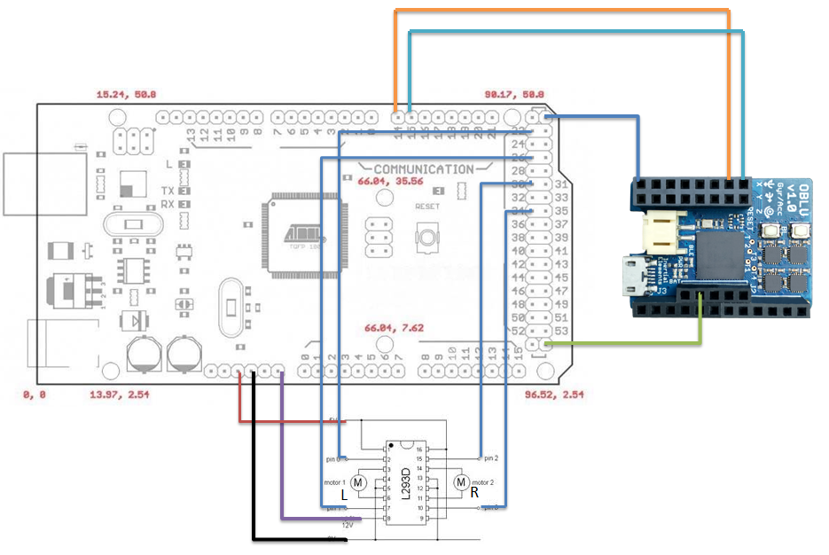
Refer below schematic diagram for detailed electrical connections between Arduino, oblu, motor driver and battery pack.
COMMUNICATION PROTOCOL:
Below is how the data communication takes place between the oblu sensor mounted on the robot and smartphone, i.e. Xoblu:
Step 1: Xoblu sends START command to oblu
Step 2: oblu acknowledges receiving command by sending appropriate ACK to Xoblu
Step 3: oblu sends DATA packet containing displacement and orientation infromation for each stride, at every step, to Xoblu. (step = whenever detects zero motion or standstill is detected).
Step 4: Xoblu acknowledges receiving last DATA packet by sending appropriate ACK to oblu. (Cycle of steps 3 and 4 is repeated until Xoblu sends STOP. On receiving STOP command, oblu executes Step 5)
Step 5: STOP - (i) Stop processing in oblu (ii) Stop all outputs in oblu
Please refer oblu's Application Note for details of START, ACK, DATA and STOP
HOW DOES OBLU IMU WORK (optional) :
Presenting some references on oblu's overview and basic principal of operation of a foot-mounted PDR sensors:
--> The available source code of oblu is targeted towards foot-mounted navigation. And it is best optimized for that purpose. Below video covers its basic principal of operation:
--> Here are couple of simple articles on foot mounted PDR sensors:
--> You may refer this document for details on pedestrian dead reckoning using foot-sensors.
--> Watch following video for the possible applications of "oblu":
----------------
Please do share your feedback, suggestions and leave comments.
Best Wishes!