Close
0%
0%

8-bit Jukebox

Chiptune Music never looked cooler!

Similar projects worth following
The 8-bit Jukebox is a chiptune music box powered by littleBits’ new Arduino module. The module is programmed with 4 different songs that playback with a retro, video-game-styled 8-bit sound.

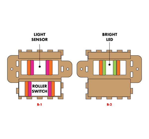
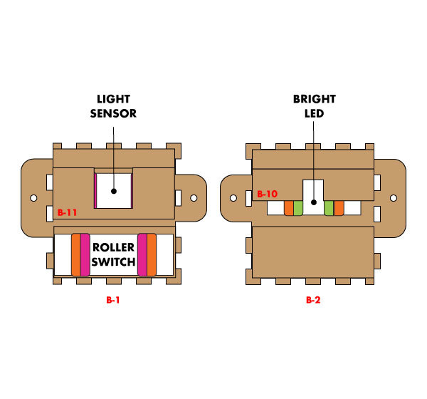
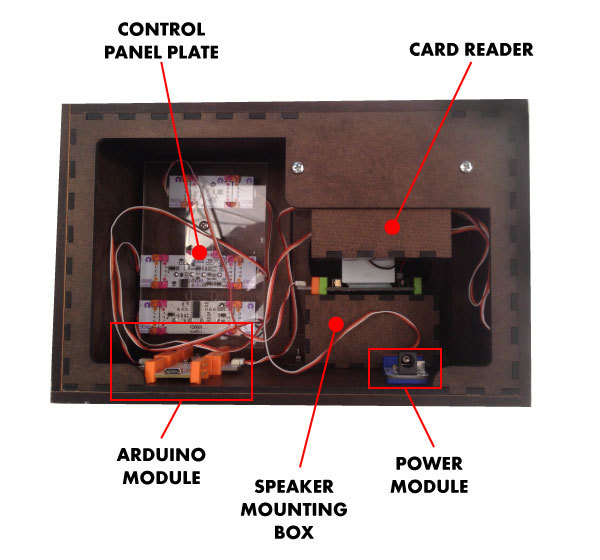
To select which song you would like to play, just insert one of the 4 song cartridges into a slot on top of the box. Embedded in each cartridge is a light filter with a different opacity. Inserting the cartridge triggers an LED to shine light through the filter, and a light sensor determines which song cartridge was inserted by reading the amount of light passing through the filter. Two different littleBits synth modules, Envelope and Delay, give you a chance to play with the audio single creating a more dynamic sound.

See it play here: https://www.youtube.com/watch?v=o97j4Lim8H8

  • 1 × arduinoBit
  • 1 × bright ledBit
  • 1 × delayBit
  • 1 × dimmerBit
  • 1 × envelopeBit

View all 17 components

  • 1
    Step 1
    1.      Assemble the case: 
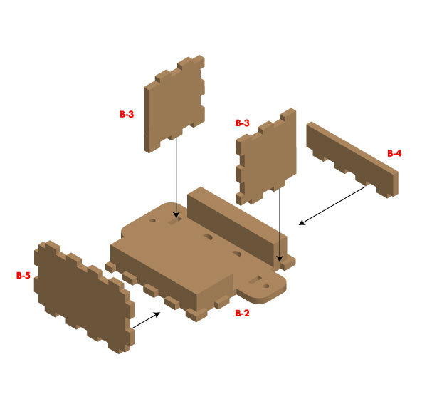
Add a little glue to the edges of each plate (A-1 through A-5) and press fit them together. The arrows and letters on plates A-1 through A-4 should match up as shown in Image 1. You might want to use some clamps if the plates don’t stay together on their own. Be sure to wipe away any excess glue that squeezes out when you press the plates together.
    2. 2.  Assemble the card reader: 

      Glue the spacer plates (B-7, B-8, B-9) to the two the front and back plates of the card reader (B-1 and B-2) as shown. Next glue the sides (B-3), top (B-4), and bottom (B-5) to the back plate (B-2) as shown. Glue the other top (B-4) to the front plate (B-1). Insert the LED, Light Sensor, Roller Switch, and Wire Modules as shown. Tape the LED spacer (B-10) to the LED Module and the Light Sensor Spacer (B-11) to the Light Sensor as shown. Add the front plate (B-1) to the back plate assembly (B-2) but do not glue them together. You might want to get into the reader later to make adjustments to the light reader.

    3. 3.  Assemble the speaker mount: 

      Add a little glue to the edges of each plate (C-1 through C-4) and press fit them together. You might want to use some clamps if the plates don’t stay together on their own. Be sure to wipe away any excess glue that squeezes out when you press the plates together.

    4. 4.  Assemble the control panel plate: 

      First create the spacer by inserting the ⅛” nut into the hole on E-3. Glue one E-2 on top of it and two E-2s below it as shown in. Be sure to wipe away any excess glue that squeezes out when you press the plates together. When this assembly has dried, use a machine screw to attach the spacer you just made to the control panel plate and add the Dimmer, Envelope, and Delay Modules as shown. Next add a dab of glue to the top of the spacer and insert the entire assembly into the case you assembled in step 1. The nobs from each module should poke out of the holes on the front plate of the case. Clamp the control panel plate to the front plate, making sure the spacer is making contact with the front plate. If you need to remove the control modules later, just unscrew the plate from the spacer.

    5. 5.  Add the speaker mount to the case: 

      Place the speaker mounting box you made in step 3 inside the case. Insert two machine screws through the small holes in the bottom of the case and up through the holes in the base of the speaker mount. Add nuts to the screws to keep the mount in place.

    6. 6.  Add the wooden facing to the case: 

      Glue F-1 and F-2 to the bottom of the case assembly. The two holes in F-1 should line up with the speaker mount screws in the bottom of the case. Both F-3 and F-4 plates should be glued to the sides of the case. Glue F-5 and F-6 to the top of the case, being sure that the card slot in F-6 goes over the hole cut out for the card reader. If you would like to sand and finish the wood facing, now is the time to do so, but remember to take the control panel modules out before you do so.

    7. 7.  Add the face plates to the case: 

      Tape or glue the fabric you would like to use for you speaker hole over the D-4 plate. Next, tape or glue this plate to the center of the speaker plate (D-1). Finally, glue the face plates (D-1, D-2, and D-3) to the case.

    8. 8.  Mount the card reader: 

      Insert the card reader into the slot cut out on the top of the case. Run the 2.5” machine screws through the holes in the rear of the case and through the tabs on either side of the card reader. Add a bolt to the end of each screw and tighten to hold the card reader in place.

    9. 9.  Add the remaining modules: 

      Place the feet of the Arduino Module in the holes on the bottom of the case. Do the same with the Power Module and use the remaining Wire Modules to complete your circuit.

    10. 10.  Create your song cards: 

      Assemble the four song cards as shown in. We experimented with a lot of translucent materials in our shop. Several layers of regular printer paper worked quite well. The silver anti-static bags that our modules ship in also worked. Whatever materials you use, you will want to be sure that each card has a different level of translucency. To measure how much light each card is letting through, upload the Card Calibration code from the link above onto your Arduino and keep the Arduino plugged into your computer. Once the code is uploaded, open the serial monitor in the Arduino IDE and insert each card into the slot. Once every second the serial monitor will show you a value between 0 and 1023. This number represents how much light is reaching the Light Sensor Module. Record this number for each of the four cards. In a moment you will use these numbers to adjust the code for the music box.

      NOTE: Try to have the values for each card as far apart as possible (e.g. 100 , 400, 700, 1000). You might need to play around with adding and subtracting layers of your translucent materials until you get numbers that work well. If the numbers are too close together, your music box will have a hard time telling the difference between the cards.

    11. 11.  Program your Arduino Module: 

      Once you have your cards made, download and open the 8-bit Music Box code that is included with these instructions. Go to the part of the code where you can calibrate your song cards. Each card has an upper limit and a lower limit. If the light sensor reading falls between these two limits, that song will play. If necessary, edit the values for these light limits so they work with the cards you have made. Be careful not to overlap these values. If you do, your songs will not play correctly.

    12. 12.  Use your new music box: 

      Now everything should be ready to go. Use your cards to listen to the songs and try adjusting the Envelope and Delay knobs to change how the music sounds.

    13. 13.  Changing the songs: 

      If you would like to change the songs on your music box, feel free to dig into the code and experiment. This sketch uses the pitches.h library. The individual notes for each song are stored in an array called melody. The durations for each note (i.e. quarter note, half note, etc…) are stored in an array called noteDurations. A value of 8 produces an eighth note, a value of 4 produces a quarter note, and so on. If you would like help translating sheet music into values for this sketch, check out this great tutorial from GarageLab:

      (http://garagelab.com/profiles/blogs/how-to-use-tone-function-arduino-playing-the-james-bond-theme

View all instructions

Enjoy this project?

Share

Discussions

Similar Projects

Does this project spark your interest?

Become a member to follow this project and never miss any updates