 Quinn
QuinnIndex of project logs which have all the details, pictures and descriptions:
- Clearing out the old
- Power strips
- Bench assembly 1
- Bench assembly 2
- ESD protection
- Monitor mounts
A personal project to overhaul my home lab setup, and install new benches
Already have an account? Log in.
To make the experience fit your profile, pick a username and tell us what interests you.
Index of project logs which have all the details, pictures and descriptions:
Installing the first shelf with the power bar meant feeding the wire into the plate, and into the upright channel, and finally connecting to the power cable.
In adjusting the spacers, I intentionally left room for this shelf to be lowered as I set it a bit higher than expected to make room for monitors. This will allow me to lower it if I ever want to without cutting the laminate again.
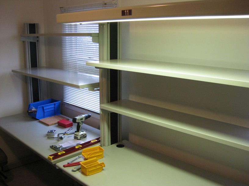
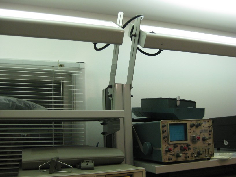
I continued with this process to add both shelves to both benches. I also installed one of the light fixtures to test out how I liked it.
The way the light fixture is attached, it comes out perpendicular to the uprights. This meant that there was not much room between the top shelf and it.
With a couple extra holes drilled into the brackets, I could adjust the angle, to have the light fixtures stick out higher.
I added two extra holes, one to make it vertical, and one at an angle. To make them even, I drilled one, then clamped it to a second to use it as a guide when drilling.
After testing, I decided I liked it best with the arms at an angle, and the fixtures pointed at the ceiling for indirect lighting. This added a lot of light to the room, without notable shadows on the bench. When the fixtures were pointing down, even with the arms at the original angle, shadows would form on the bench from the shelves, or equipment on them.
I wired the lamps in series, and to a plug instead of wiring it into the upright. This is so that I can put in a separate switch to control both of them instead of needing to reach up to the switches on the lamps themselves.
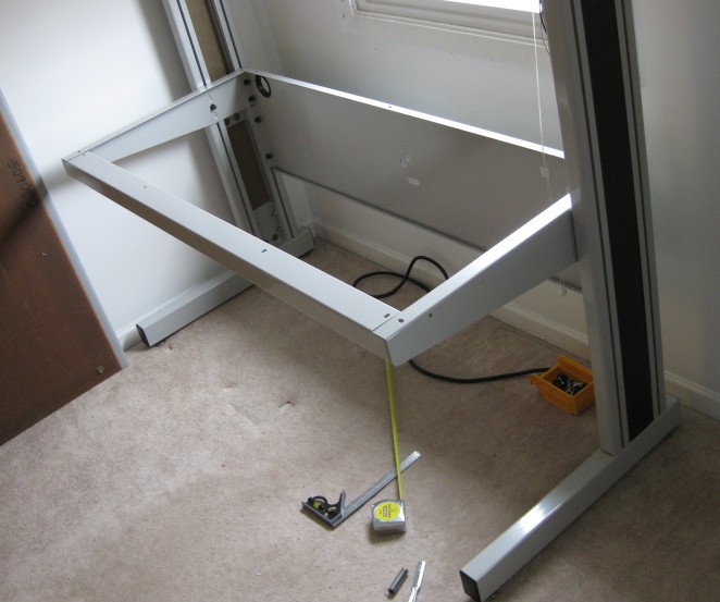
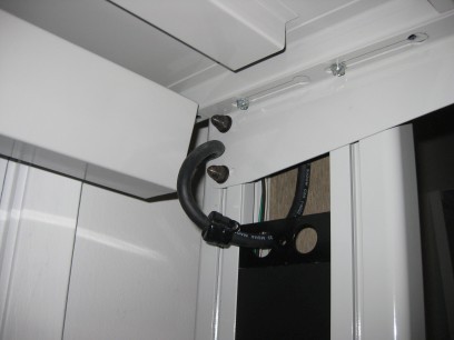
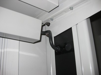
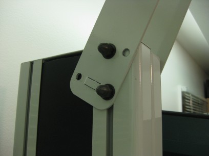
The central part of the bench are left and right uprights. (please pardon the terrible off angle picture.
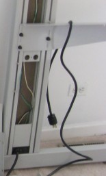
These are made of two steel extrusions, welded to a bottom bar with leveling feet. Along the sides of the extrusions are T-slots which bolts slide into so that shelves and other things can be bolted on. Shown in the picture above is the support arm for the desk surface, bolted in place. Also shown at the bottom is a power cable inlet, leading to wires in the upright. The extrusions have slots for a plastic laminate panel to slide into to cover the opening. They are slid into place later. The panels are on both sides, but the outside panel didn't need to be removed for assembly.
Here is a picture of the extrusions from the top(this is two of the uprights placed next to each other) which should make the bolt channels and laminate slots clear. (This picture is from later in the process)
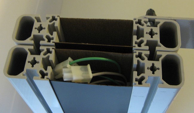
The slots are made for carriage bolts, with the heads slipping into the widen part, and the square shoulder of the bolt preventing rotation in the slot. These have to be slid down from the top, so you have to either assemble the shelves and other items from the bottom up, or plan ahead how many bolts you'll need.
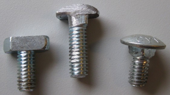
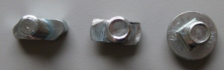
A second type of bolt was used in the system, which were intermixed. I'm not sure how they were originally designed, but it used more of these than the carriage bolts. This is a T shape, which can be inserted into the slot from the side, and twisted to lock. It is quite thick, so I expect just as strong. In practice though, they were a bit of a nuisance to use, as during assembly, they could wiggle back and when tightened, not engage. It just took extra care to make sure it was engaged each time. The T part is long enough such that it won't rotate more than about 45 degrees in the channel.
One of the things I knew I wanted to do was attach some swinging monitor arms, but I was not yet sure where they would go until I started placing some of my equipment. Added to this, the bracket that they were mounted to was much thicker, and the 1/2" bolts that came with the benches would not be long enough. A previous owner actually had taken some hex head bolts, and ground two sides down so that it would fit into the slots later. While a similar idea to the T bolts, it was not wide enough to prevent rotation, so would be very difficult to get to stay engaged.
Thinking about the problem a little, I came up with a solution with some longer carriage bolts. I would also grind the sides down so that they would fit in the slots. But the square shoulder would prevent it from rotating part way to get it to engage. I realized that if I ground two of the corners of the square shoulder, it would rotate 90 degrees, only in the direction I wanted it to.
The three bolts:
As I learned from a mistake during my disassembly when I purchased them, the first part that needed to go in was the back support brace. It simply fit into slotted bolts, and pulled tight. After this, a very heavy duty bar at the front to hold any weight at the front of the desk.
This mistake I had made when originally disassembling was to remove the back brace before the table top, which caused the uprights to tilt over, and partly pull several of the screw inserts out of the top. The top is wood, and has threaded inserts on the bottom. Machine screws fit up through the arms, front brace and back brace into it to hold the top into place. The top isn't really structural, so these were not intended for forces like that. Needless to say, when I disassembled the second one, I took off the table top before the back support.
This did mean I needed to repair the ones I ripped out. At this point, I placed the top in place, lined up to the screws that were remaining, and then drilled new holes from the bottom, through the arms, and into the wood. At first a pilot drill, then I removed the top to drill the finished hole. This was partly because the steel is quite thick, and because the hole in the wood needed to...
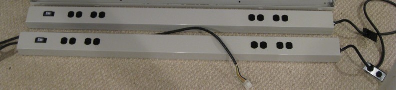
Read more »The power strips that came with the benches are built like tanks, with wiring that integrated neatly into the side uprights, which is all wonderful. Here is the pair as originally configured. Power came in from the left(of this picture), passed through the bottom strip, out the right, and into the right of the second. This wiring went inside the uprights when installed. The metal brackets seen on the wiring were plates that slid into the uprights.
However they were designed to sit on top of, and at the back edge of the desktop and first shelf. I didn't like this because it meant I couldn't have equipment hanging slightly over the back, and made the shelves effectively smaller. I wanted to adjust so that they hung under the shelves at the back, and to avoid interfering with the equipment, I wanted to only install one, under the lower shelf. Doing this wasn't too much trouble, but did mean I needed to change it's wiring. Further, as each strip only had 8 sockets, a single strip was not enough, and I wanted to add some extra sockets. While I was add it, I figured I'd wire them as GFCI protected.
The original insides:
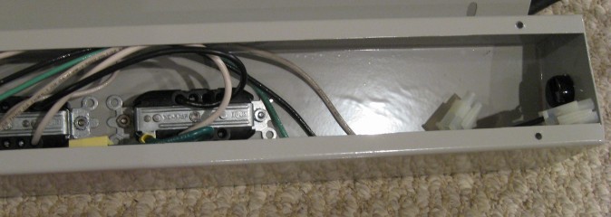
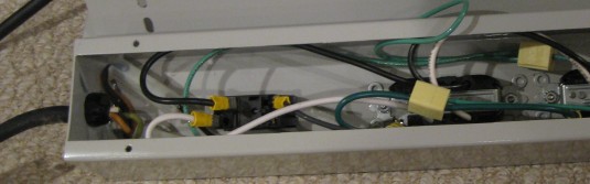
The system was very modular, with connectors on each end, and wired as pass through. The connectors are white in the above pictures. This meant that to change the input from one side to the other(which I had to do because I flipped it upside down), I simply had to disconnect it on one end, move the cable clamp and wire to the other, and plug it back in. In the process I wanted to add sockets, and adjust wiring to have them all protected by a GFCI socket. To start, I removed all the wiring, and modified the metal for the extra sockets.
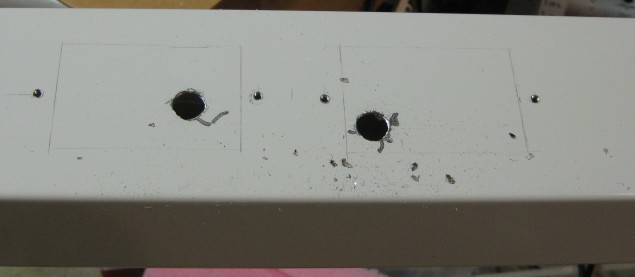
The screw holes for the sockets were drilled and tapped to accept standard wall outlets.
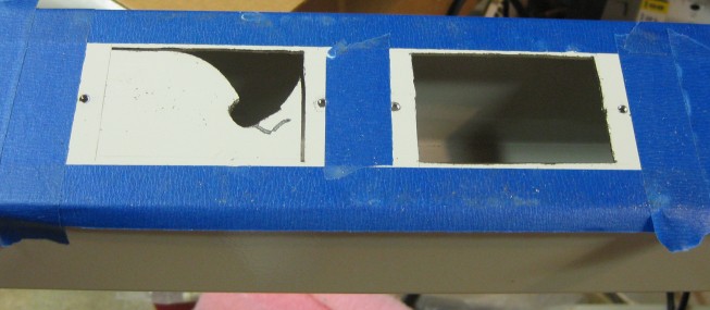
The cut outs were drawn on the metal, and pilot holes drilled to cut them with a jigsaw with a metal cutting bit. This is thick metal so took some work. Before working with the jig saw, I taped around the holes so I wouldn't scratch the paint. Cuts in progress:
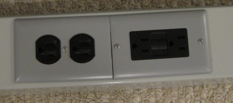
Mounting the sockets and using standard cover plates finished the job nicely:
The finished power strips simply screwed onto the back of the shelves, and the wiring entered the right side upright as it was designed for. Together, these were rather unwieldy, given the combined weight, but I was later able to get them into place.
For the start, I had to clear out all the old. I pulled a bunch of boxes from storage, and started taking everything off my old work table, under it, and around it, emptying that half of the room. The other half has parts and equipment storage, which I'm leaving as is for the moment. It'll need cleanup as well, but one part at a time made sense.
The old work table, after cleaning it all up, and vacuuming varios wire scraps, lost screws, etc out of the carpet from years of use:
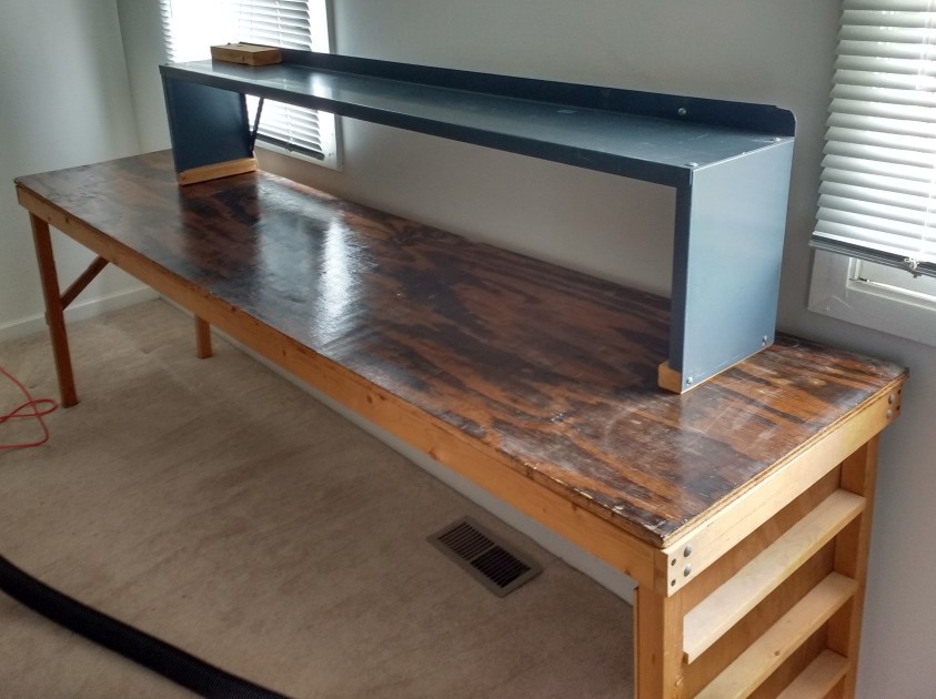
The old table was not big enough, was not ESD safe, and was no where near strong enough. I had to limit what I could put on it to keep it from sagging. Even still, after years of use, the center had sagged about an inch lower than the ends. This was also poor construction and while it wasn't going to fall over, it was wobbly. I made this bench when I was a child, as half of a train table. Given it's original lightweight purpose, and how young I was when I built it, it's understandable that it was so poorly constructed. The metal top shelf was something I scavenged afterwards, which was helpful, but nowhere near enough.
The work benches I was going to install I had purchased as surplus 3 years prior, but they had been sitting in storage, waiting for me to have enough time to embark on this project. They were a fantastic deal as I paid $50 for each, and they were only a handful of years old at the time. I couldn't find the brand of them, so I'm not sure their cost new, but I expect it was substantial.
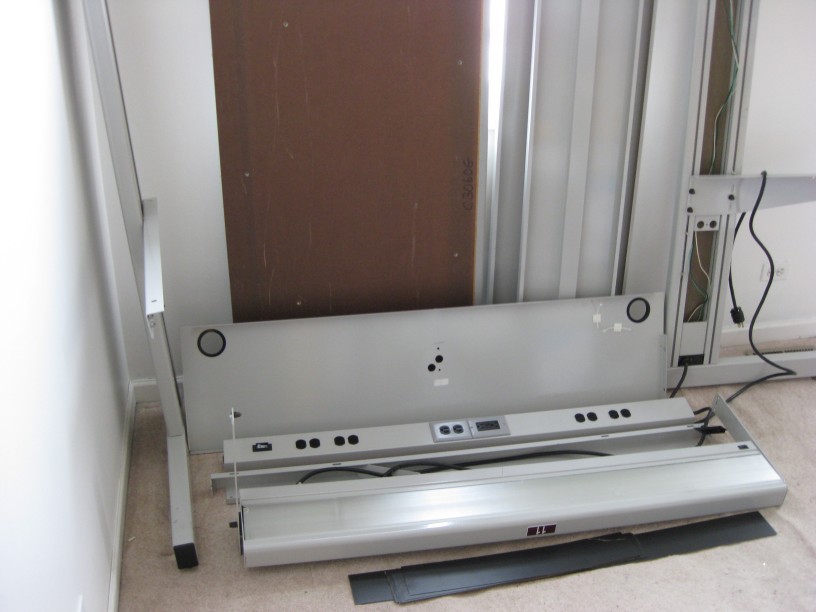
This is a very heavy weight bench, weighing probably over 300 pounds assembled. It is all steel, plus the table top. All of the metal work is 12 to 8 gauge steel, plus the uprights which are steel extrusions. The above picture shows the uprights at left and right. Top center is the table top(bottom side) and two of the shelves next to it. Below this is a back panel for rigidity, followed by the power strips(this picture after modifications), another support brace, the overhead lamp, and the laminate cover pieces. Every one of these pieces is surprisingly heavy.

 ReidDye
 Mike Szczys