 Quinn
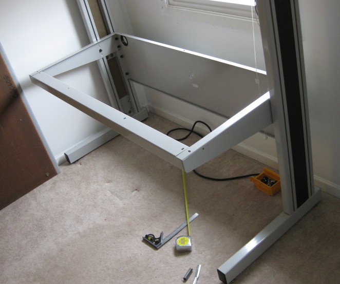
QuinnThe central part of the bench are left and right uprights. (please pardon the terrible off angle picture.
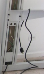
These are made of two steel extrusions, welded to a bottom bar with leveling feet. Along the sides of the extrusions are T-slots which bolts slide into so that shelves and other things can be bolted on. Shown in the picture above is the support arm for the desk surface, bolted in place. Also shown at the bottom is a power cable inlet, leading to wires in the upright. The extrusions have slots for a plastic laminate panel to slide into to cover the opening. They are slid into place later. The panels are on both sides, but the outside panel didn't need to be removed for assembly.
Here is a picture of the extrusions from the top(this is two of the uprights placed next to each other) which should make the bolt channels and laminate slots clear. (This picture is from later in the process)
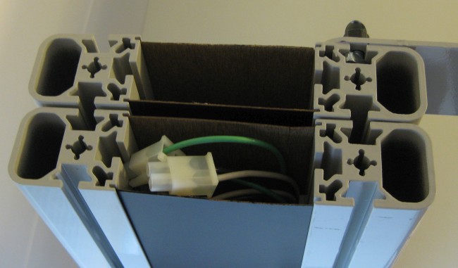
The slots are made for carriage bolts, with the heads slipping into the widen part, and the square shoulder of the bolt preventing rotation in the slot. These have to be slid down from the top, so you have to either assemble the shelves and other items from the bottom up, or plan ahead how many bolts you'll need.
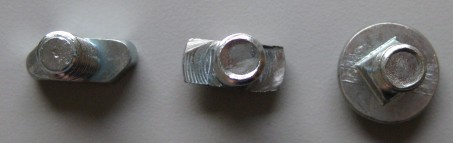
A second type of bolt was used in the system, which were intermixed. I'm not sure how they were originally designed, but it used more of these than the carriage bolts. This is a T shape, which can be inserted into the slot from the side, and twisted to lock. It is quite thick, so I expect just as strong. In practice though, they were a bit of a nuisance to use, as during assembly, they could wiggle back and when tightened, not engage. It just took extra care to make sure it was engaged each time. The T part is long enough such that it won't rotate more than about 45 degrees in the channel.
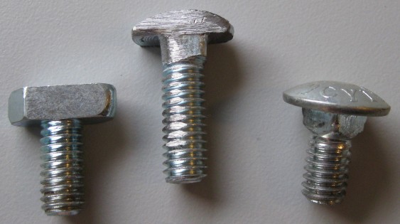
One of the things I knew I wanted to do was attach some swinging monitor arms, but I was not yet sure where they would go until I started placing some of my equipment. Added to this, the bracket that they were mounted to was much thicker, and the 1/2" bolts that came with the benches would not be long enough. A previous owner actually had taken some hex head bolts, and ground two sides down so that it would fit into the slots later. While a similar idea to the T bolts, it was not wide enough to prevent rotation, so would be very difficult to get to stay engaged.
Thinking about the problem a little, I came up with a solution with some longer carriage bolts. I would also grind the sides down so that they would fit in the slots. But the square shoulder would prevent it from rotating part way to get it to engage. I realized that if I ground two of the corners of the square shoulder, it would rotate 90 degrees, only in the direction I wanted it to.
The three bolts:
As I learned from a mistake during my disassembly when I purchased them, the first part that needed to go in was the back support brace. It simply fit into slotted bolts, and pulled tight. After this, a very heavy duty bar at the front to hold any weight at the front of the desk.
This mistake I had made when originally disassembling was to remove the back brace before the table top, which caused the uprights to tilt over, and partly pull several of the screw inserts out of the top. The top is wood, and has threaded inserts on the bottom. Machine screws fit up through the arms, front brace and back brace into it to hold the top into place. The top isn't really structural, so these were not intended for forces like that. Needless to say, when I disassembled the second one, I took off the table top before the back support.
This did mean I needed to repair the ones I ripped out. At this point, I placed the top in place, lined up to the screws that were remaining, and then drilled new holes from the bottom, through the arms, and into the wood. At first a pilot drill, then I removed the top to drill the finished hole. This was partly because the steel is quite thick, and because the hole in the wood needed to only to part way through. I threaded the inserts into my new holes, and installed the tabletop. Having several of the mounting points shifted a little won't have any negative performance effect.
With the table in place, I moved onto the first shelf. To make it much easier, I removed the brackets from the shelf, and installed them separately, again taking extra care to ensure they were at matched heights, and at right angles to the uprights. I used one of the carriage bolts, and one of the T bolts to make it easier to align and retain more flexibility in the future.
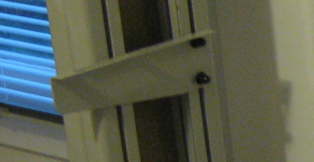
Before installing the shelf, I attached the modified power strip to the bottom. The power cable comes out of the power strip, and then enters the upright through one of these brackets.
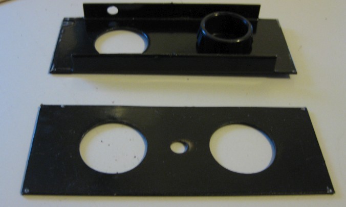
These are two styles of the same thing. I'm not sure why one has the extra bracing. These slide down the channel that the plastic laminate fits into. As this is installed from the top only, I needed to measure, and put the right size laminate piece into the channel first. As I've changed the position of the power bars and the shelves, it meant I had to adjust the length of the laminate.
Having worked with plastic laminate before when building my stand up MAME cabinet, I knew that for simple cuts like this, I could cut it with a utility knife and straight edge. I used some scrap wood as a cutting surface.
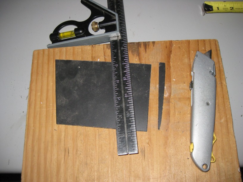
It is as simple as lining up the straight edge, and starting with a score. Don't try to cut through the whole thing, but instead, bits at a time as you go. I found it to be a cleaner edge if I just kept going until I was all the way through. You could score part way and then snap it, but this often leaves a bit of a jagged edge you have to clean up afterwards. This method leaves an edge which is more of a light brown from the inner material than the black of the outside, which I simply colored in with a black sharpie.
Discussions
Become a Hackaday.io Member
Create an account to leave a comment. Already have an account? Log In.