 David Levi
See the building process and final theremin in the ~90 second video below:
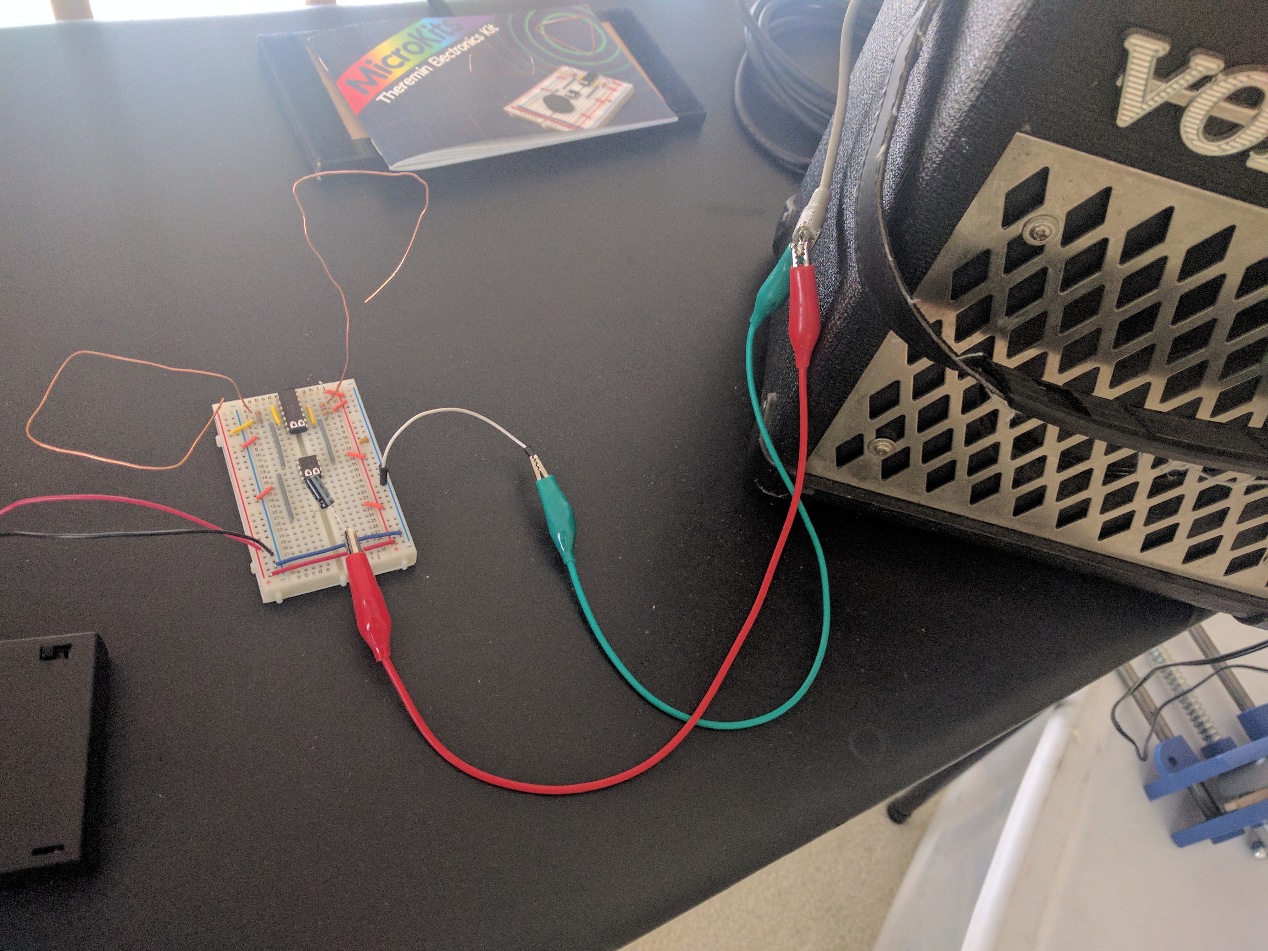
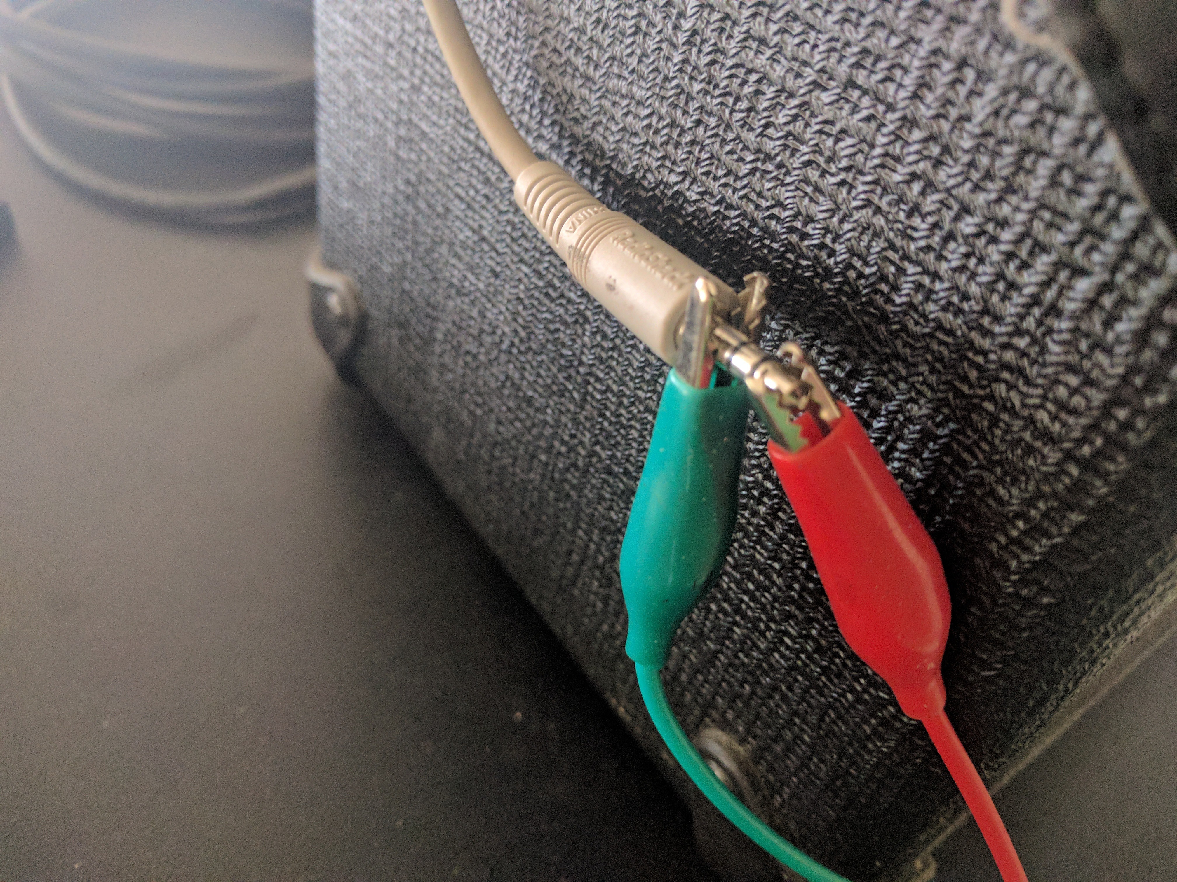
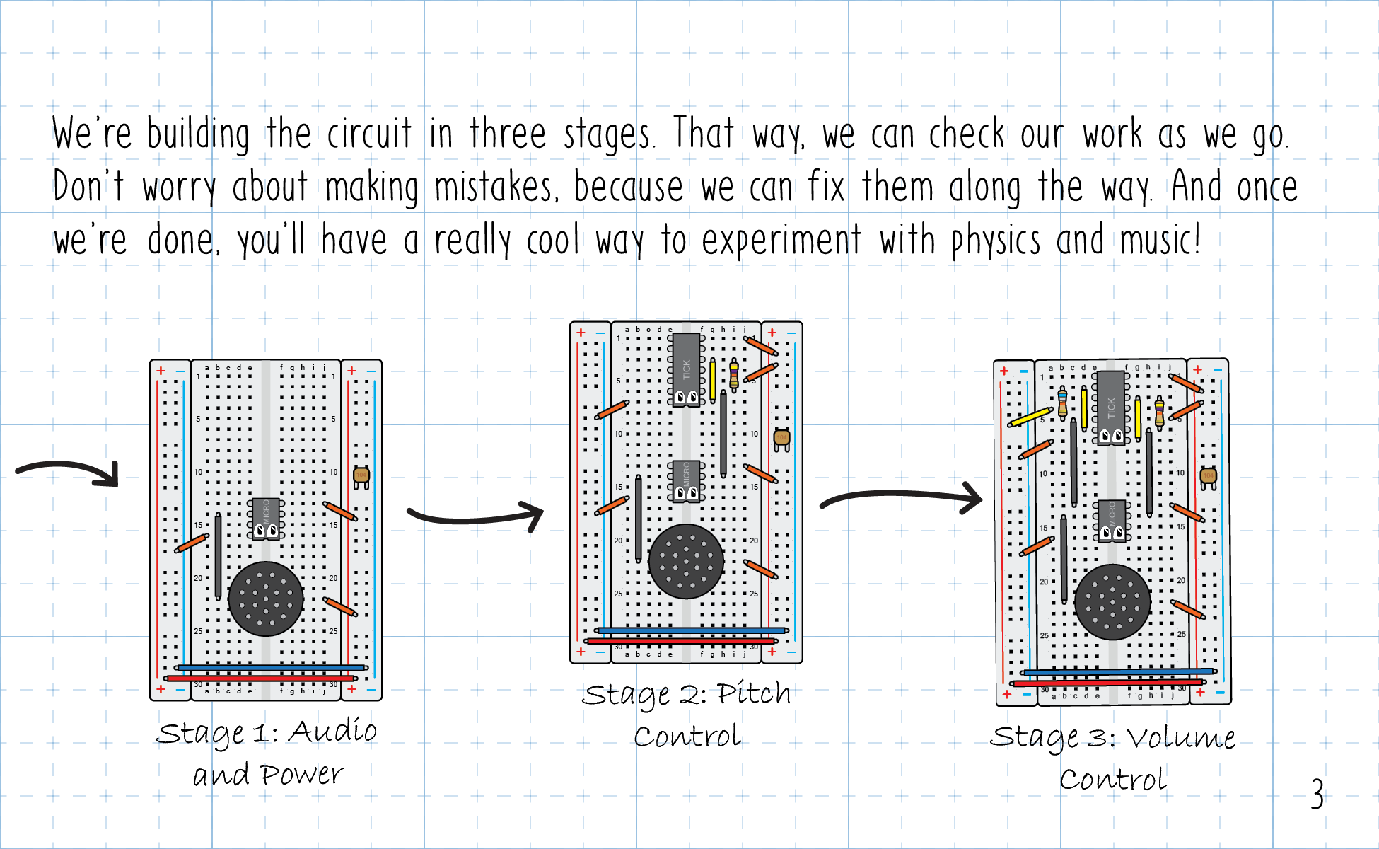
And here's a handy GIF that shows how the kit is assembled step by step:
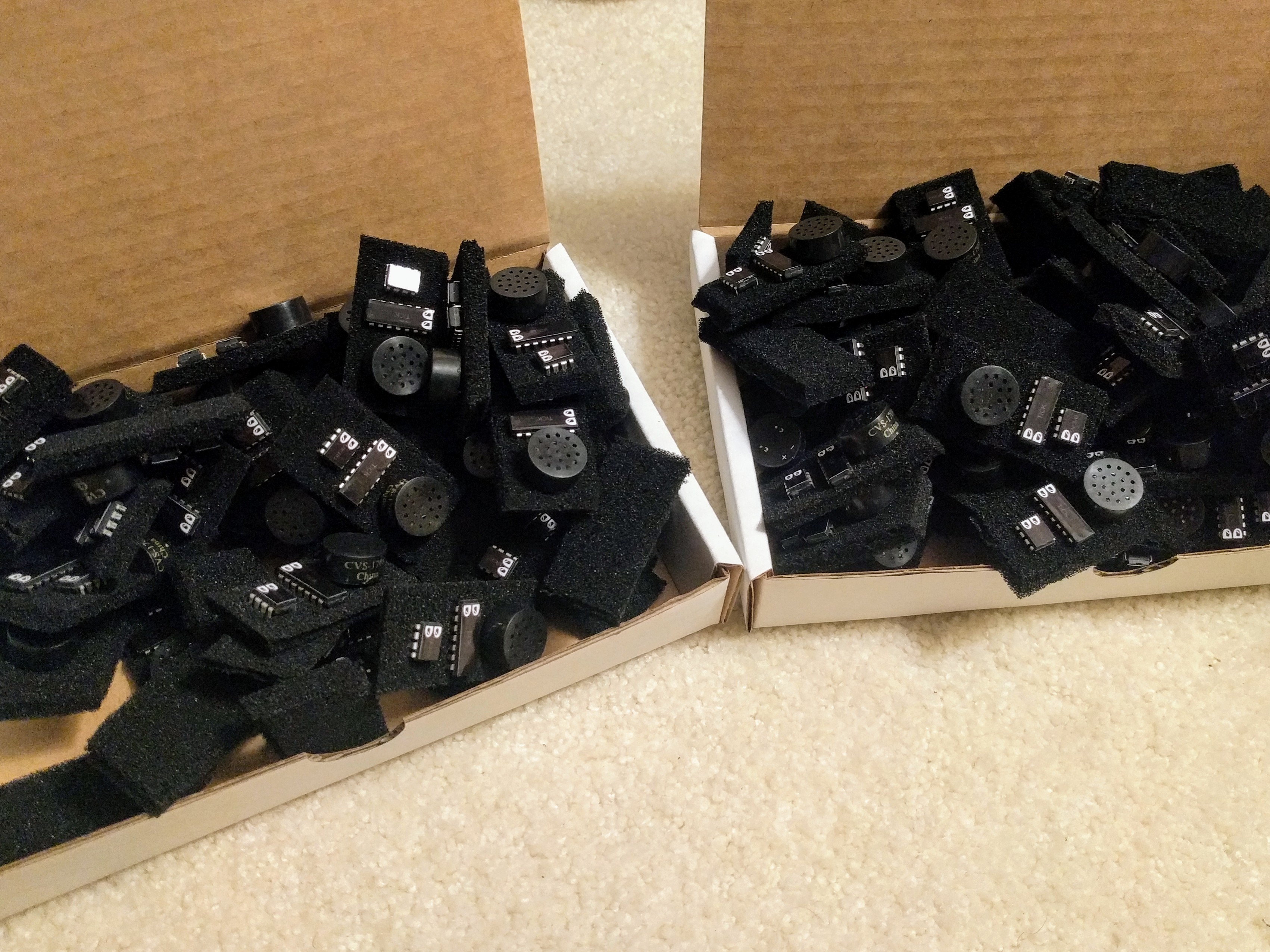
Read below to learn more about the design and assembly that's gone into these kits. Currently, we're preparing our first batch of 100 kits. Some of these kits will go directly to schools, and some will be sold at the MicroKits website MicroKits.cc
See the "Files" section just below to check out the instructional booklet!
 You will need:
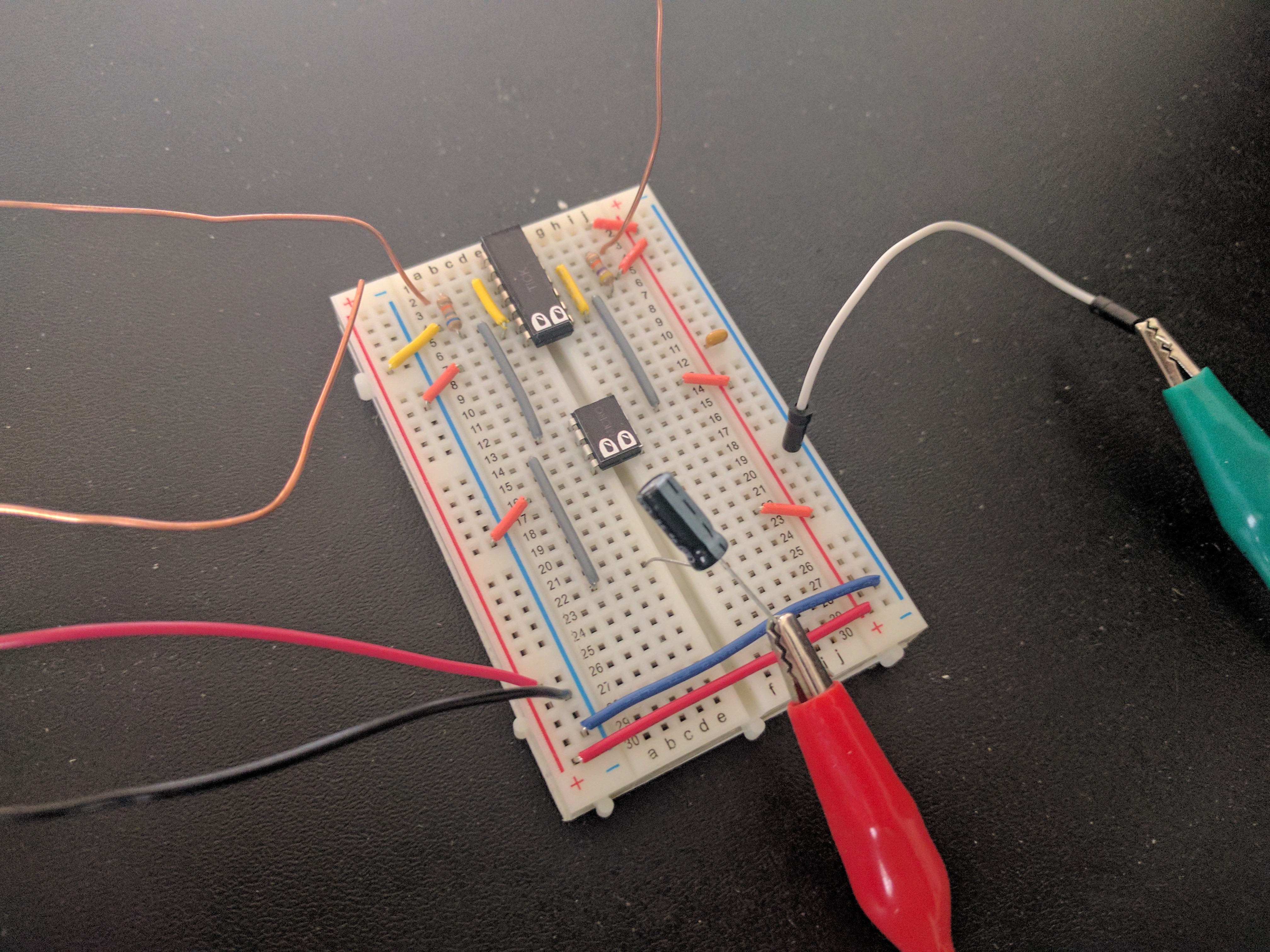


 doctek
 John Wetzel
 Gabriel D'Espindula
A very interesting project. It's a shame you left him.
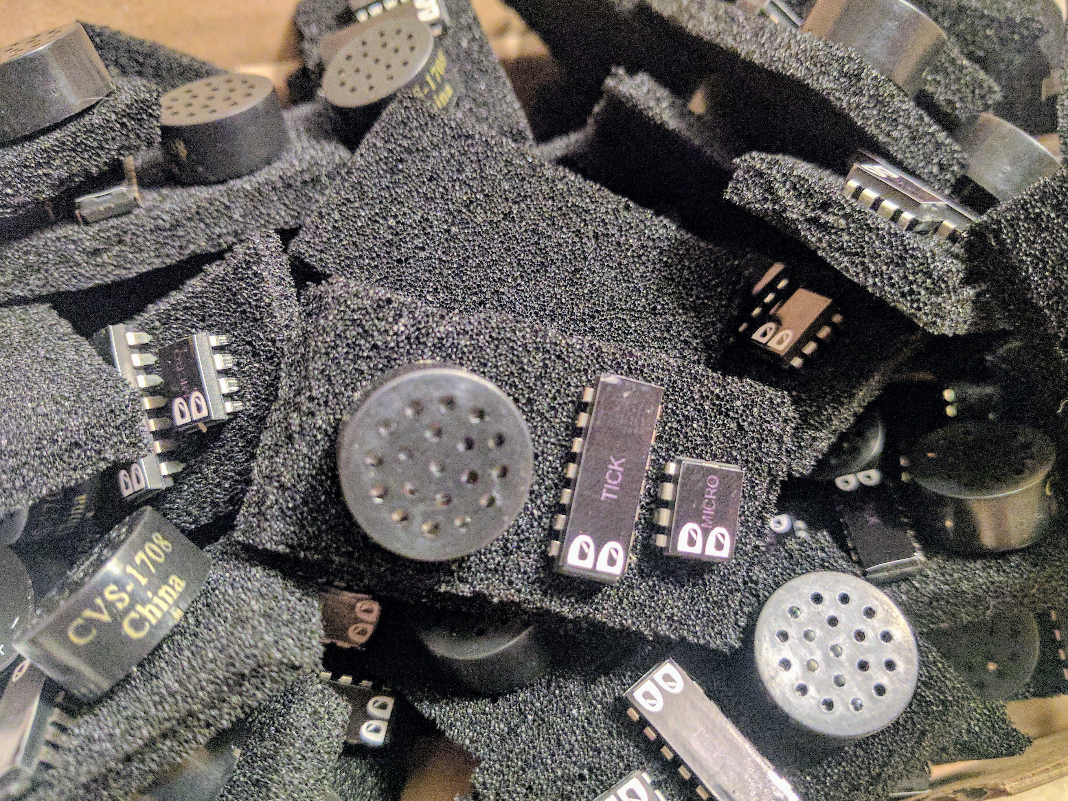
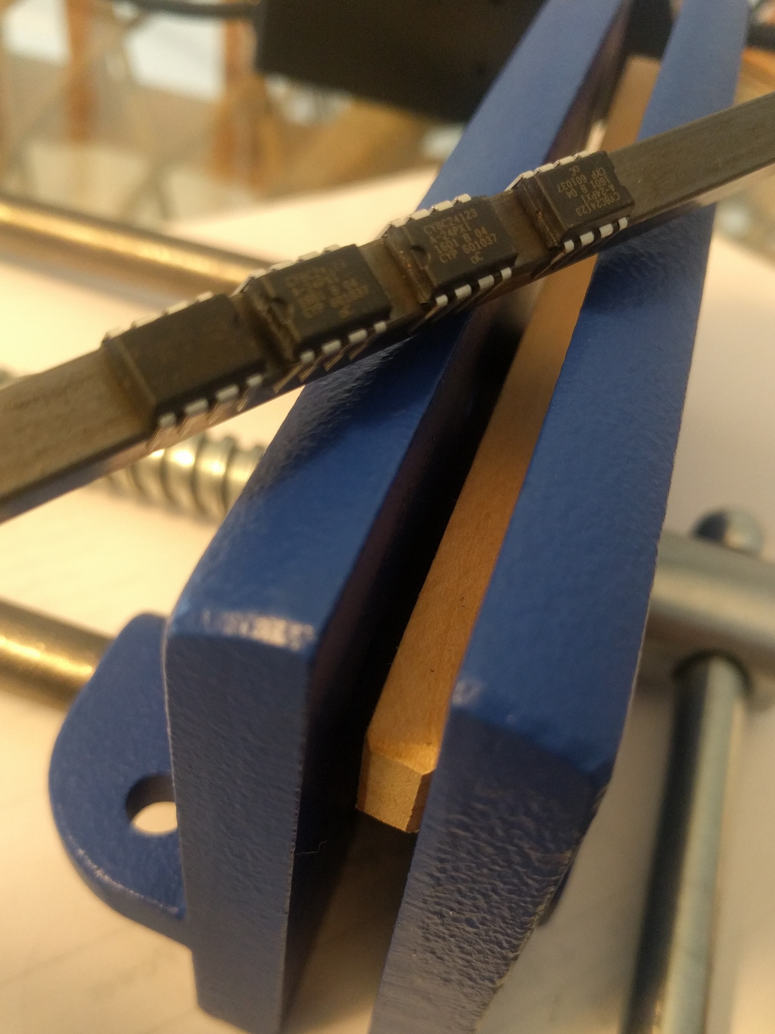
Please tell me what can be used to replace CY8C24123A24PXI - unfortunately, it is not possible to buy it. And where can I get the file of its firmware.