 David Levi
I just put together a board that I can use to easily program and test the microprocessor I use in this kit. Check it out:
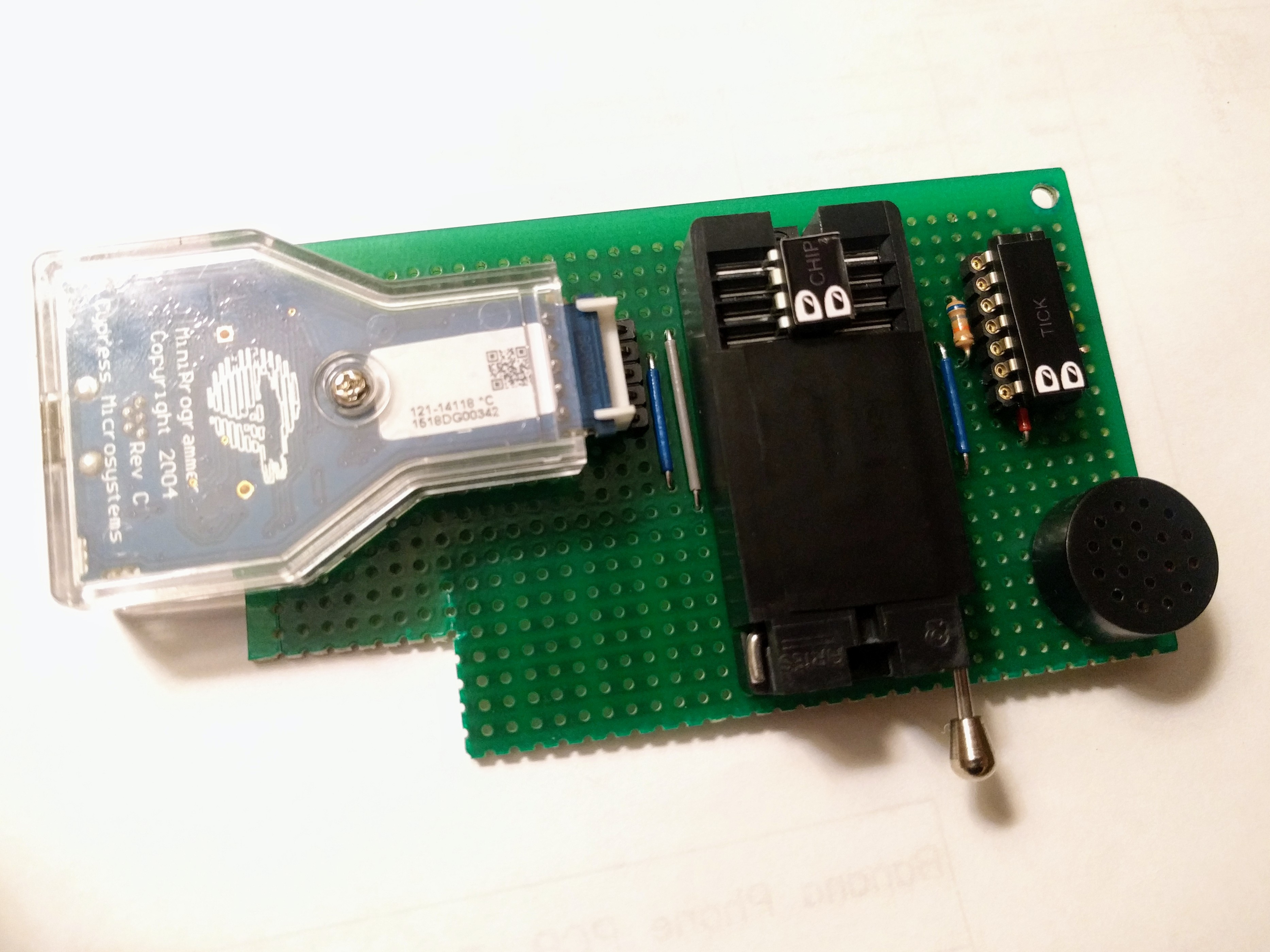
The board is pretty simple. On the right, I recreated the 555 timer circuit, to create the frequency signals that the microprocessor takes in. I also added the speaker for output. It's all the same as the kit, but soldered in place. On the left, a PSoC MiniProg programmer connects to a row of header pins. This part provides power to the circuit and programs the blank chips.
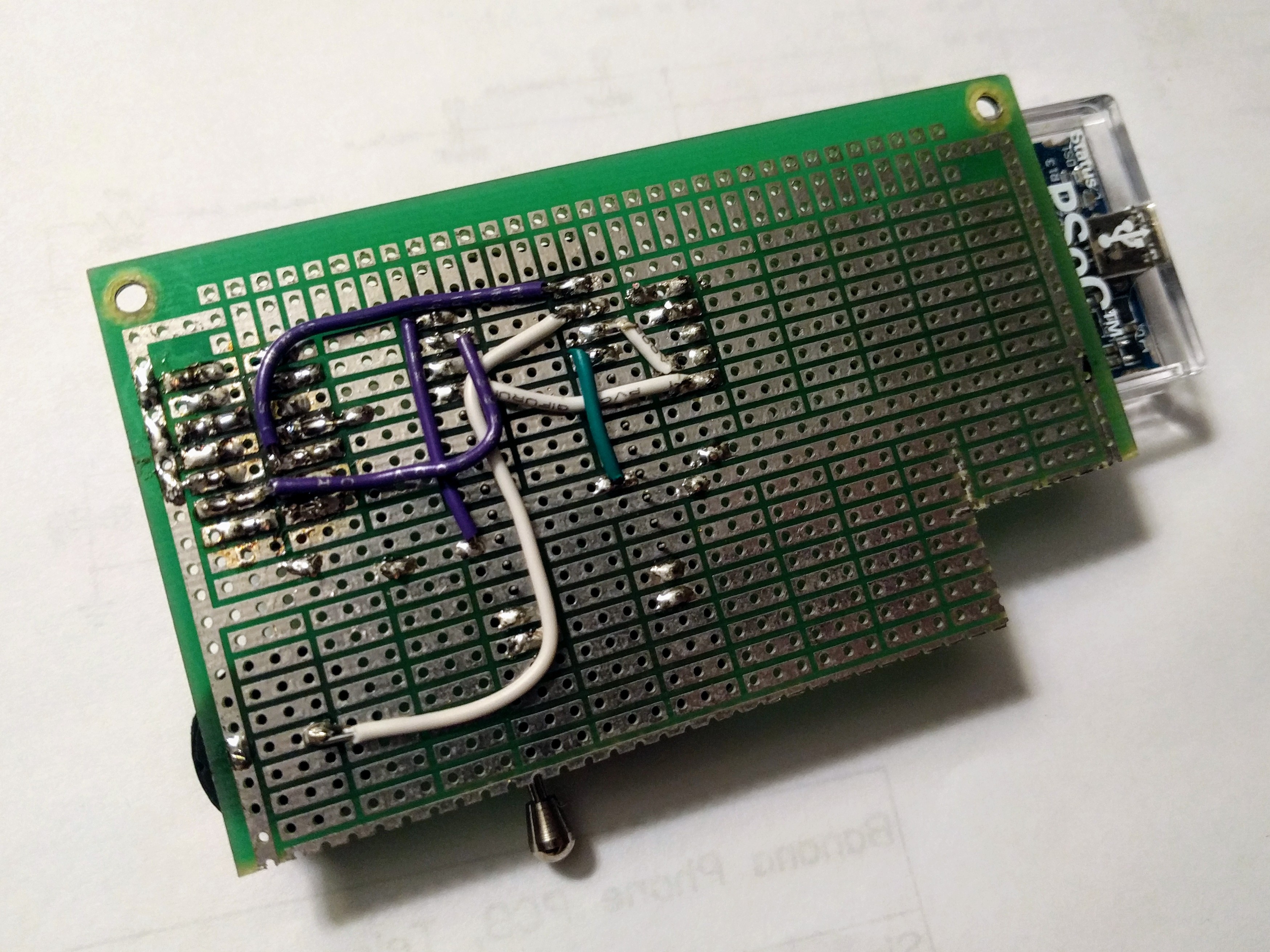
The actual microprocessor fits into a Zero Insertion Force (ZIF) holder. A ZIF uses a lever to grab onto the legs of the chip, making it really easy connect and disconnect the target chip. Underneath the ZIF, wires connect it all together.
There's no space for antennas on the board, so for now I move my finger around the 555 timer to make sure the whole part is working. At some point I should program a separate processor to create the test signals, but this will work well for now. All I have to do is mount this board onto a sturdy piece of wood, and this little rig will last the first few hundred kits I put together.
Discussions
Become a Hackaday.io Member
Create an account to leave a comment. Already have an account? Log In.