 Adellar Irankunda
This project is about the creation of an interactive (touch) board with modular and wireless capabilities. You may ask why someone would want to do this and the answer is, current interactive boards are wired, which means they have to be next or close to the computers that they are controlling. Another problem with current interactive boards is that they come in fixed sizes, something that makes them hard to move and static (if you want a different size, you have to buy a whole new smart board). The final major issue with interactive boards is that they are expensive, with most costing in the thousands of dollars that makes them expensive and inaccessible to most. With the creation of this interactive board, the size and wired constraints are addressed with its wireless and modular features. The issue of price diminishes, considering that this interactive board costs fifty dollars ($50) to produce.
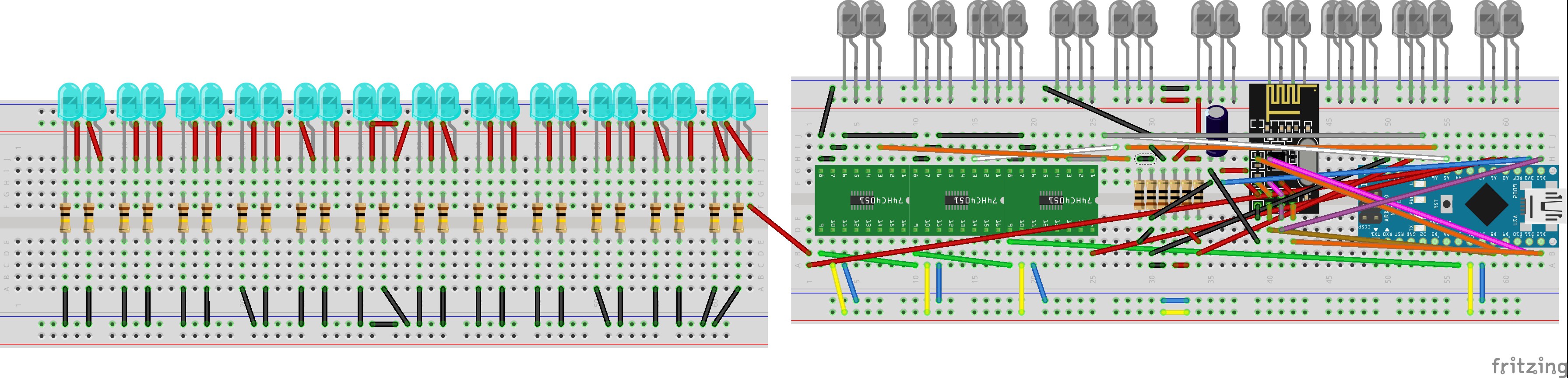
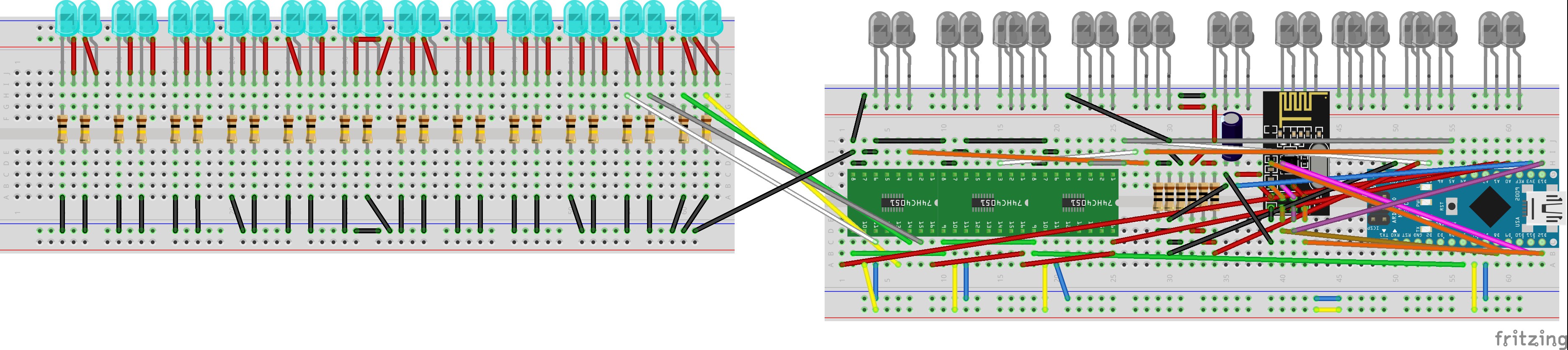
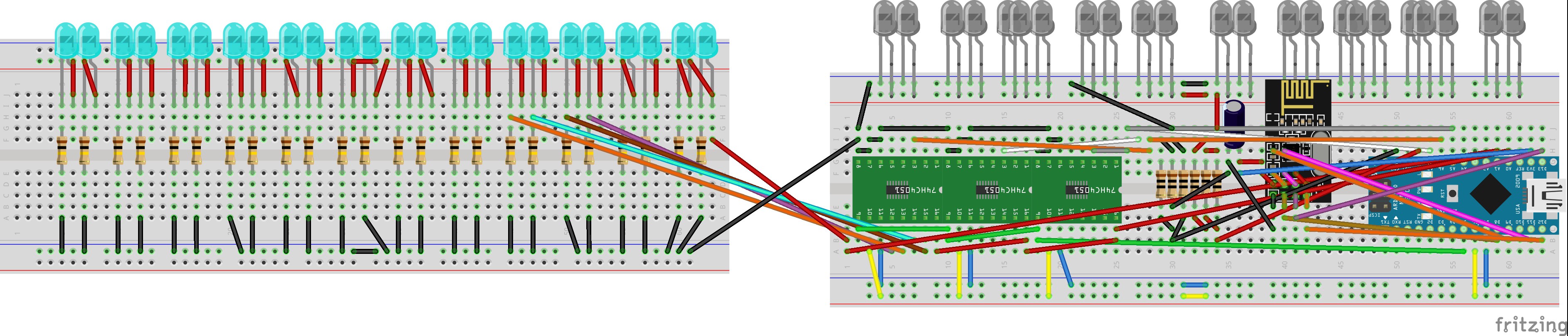
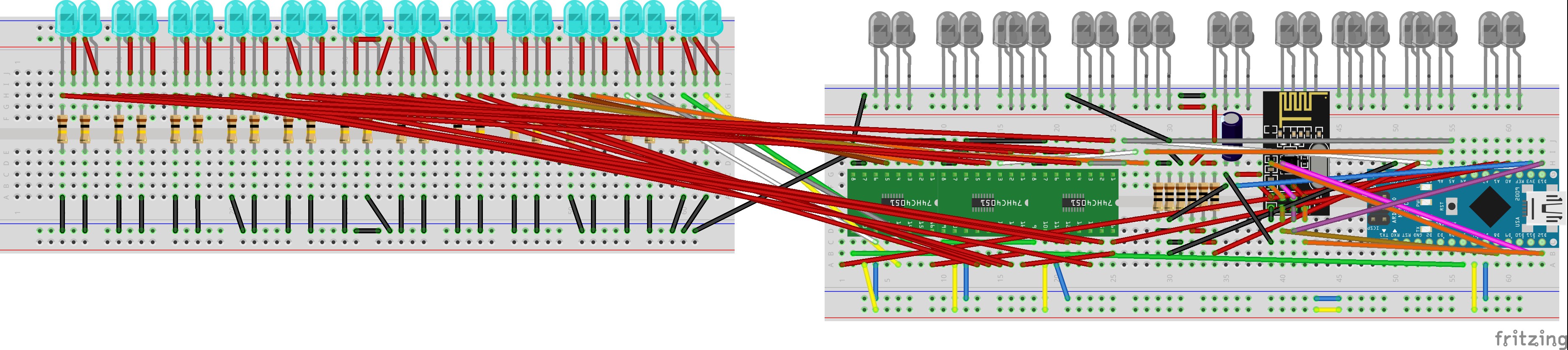
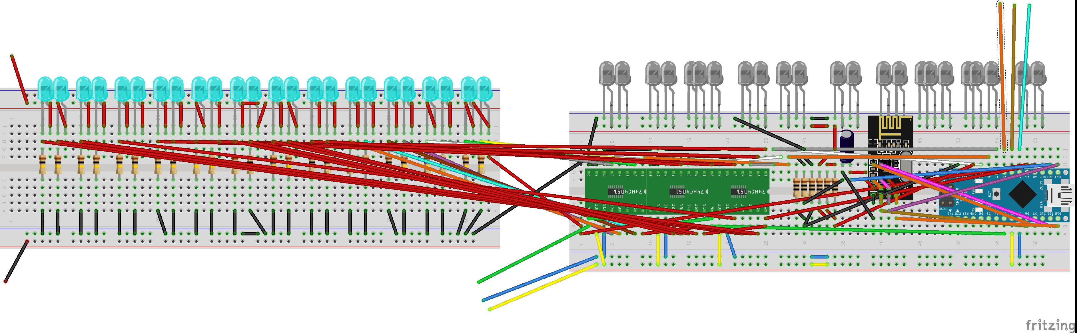
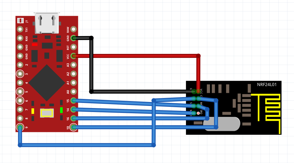
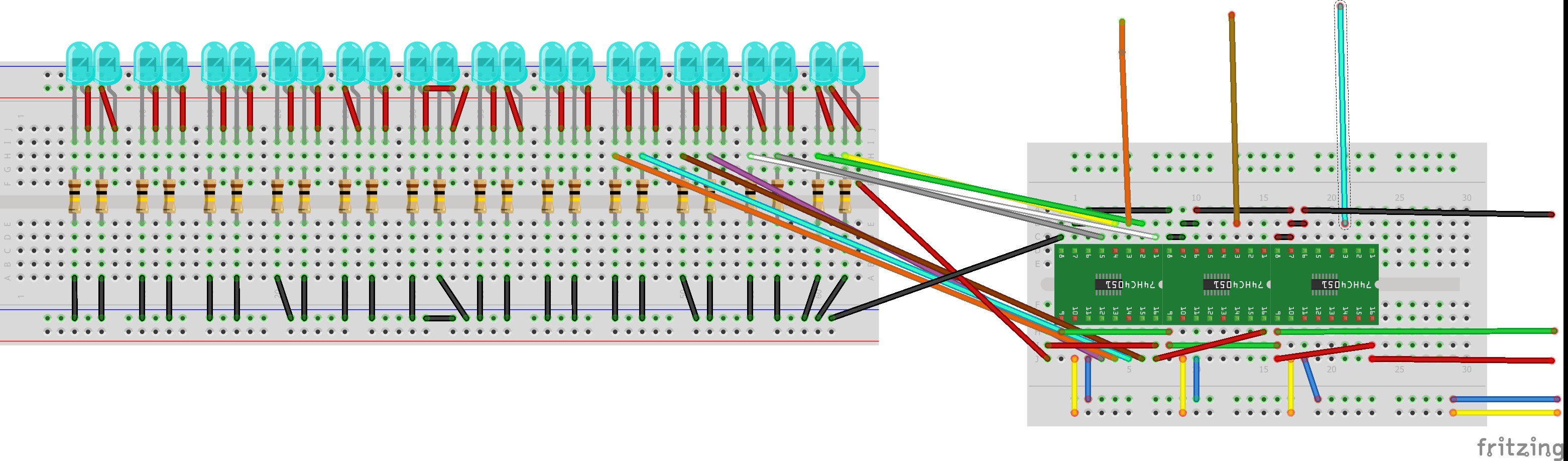
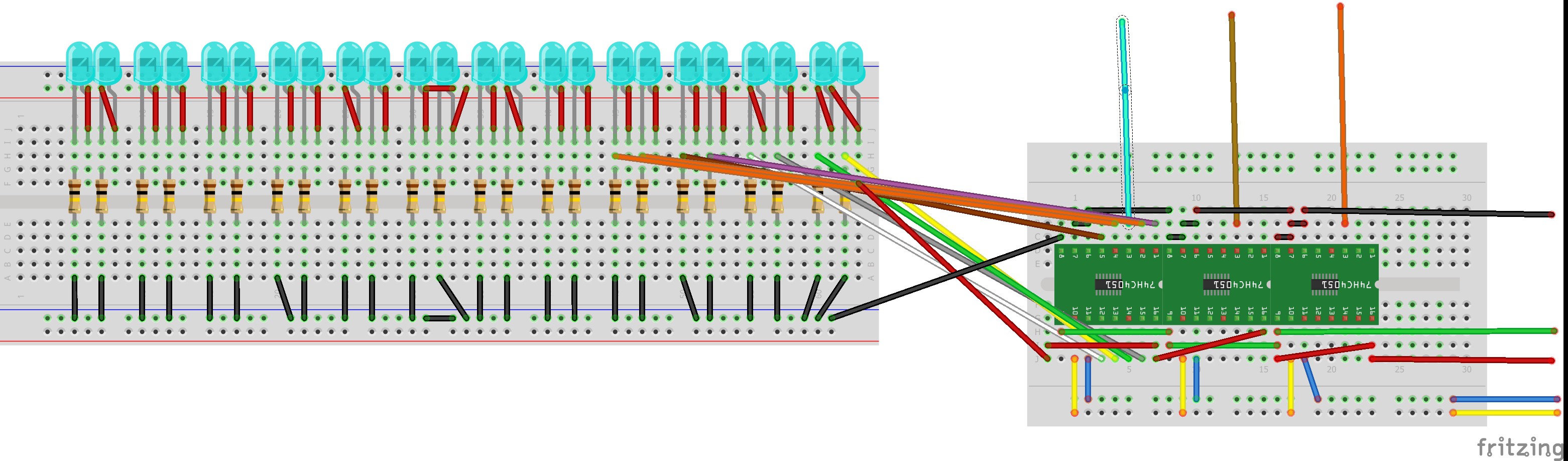
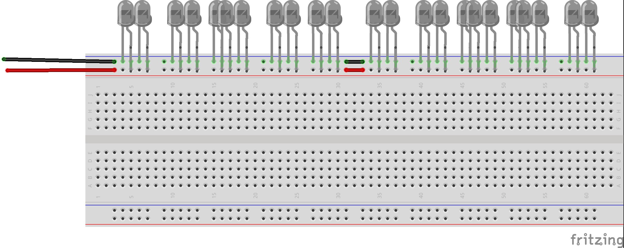
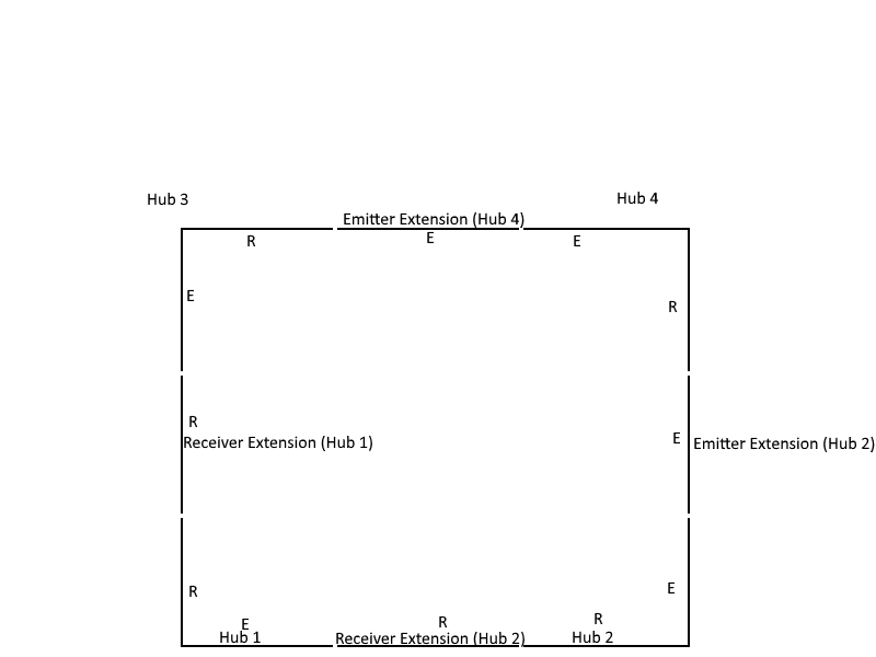
The project is centered on the creation of this interactive touch interface using infrared sensors and emitters. There is a multitude of components involved in this project so to start off, it is best to go over how the main components are connected and how the communicate. Controlling each one of the 4 sensor hubs are Arduino Nanos. The Nanos read data from [24+] infrared phototransistors via multiplexers, as the Nanos only have 8 analog pins and the minimum number of sensors is 24. The Nanos are running programs that analyze the values from each individual sensor to determine whether or not it should be considered as a point where a touch occurred. After the analysis, each one of the 4 sensor microcontrollers sends data to a Pro Micro which does a further analysis and moves the mouse in correspondence to the sensor that has detected a touch. The communication between the 4 Nanos and the Pro Micro is achieved through the use of radio transceivers. Each one of the 4 Nanos is programmed to provide power to at least 24 infrared emitters which provide light for the phototransistors. Upon building a system like this, one is able to achieve the capabilities of a wireless interactive touch display; there are software features programmed into the system to avoid shadows setting of touches, but that will be covered in the software section.
A demonstration of the latest iteration of this wireless interactive touch board is available through a video I posted on YouTube of me using it to achieve a task. In the video, I use my finger and a pen as input devices for the touch interface.
In the second video, I showcase the hardware used in the project and its modular nature by resizing it via removing an extension hub.
Features
Cost - One major drawback of interactive touch boards is their cost, the touch boards that are available today have price ranges around $1,000 - $5,000. This is a price range that is not easily accessible to the common consumer, so when working on this project I made cost a major focus of the work. The total cost to build this project is $50, this is 2,000 -10,000% cost reduction; this price cut makes it easily accessible to the everyday consumer.
· Compatibility - Yet another issue with commercially available interactive boards is their lack of universal compatibility. The compatibility of these systems is hindered due to them being dependent on drivers that need to be present on the operating system of the computer they are connected to. The "drivers" in this system are essentially embedded on the Arduino chips that are involved in their operation. This means that this system is able to function regardless of the operating system of the computer it is controlling. The user is not required to download drivers online or install drivers from a disk. This is the definition of plug-and-go.
· Versatility - Another major gripe of current interactive touch systems is their lack of versatility, this term has many implications in an interactive touch system. Versatility means being able to seamlessly move the system from one area...
Read more »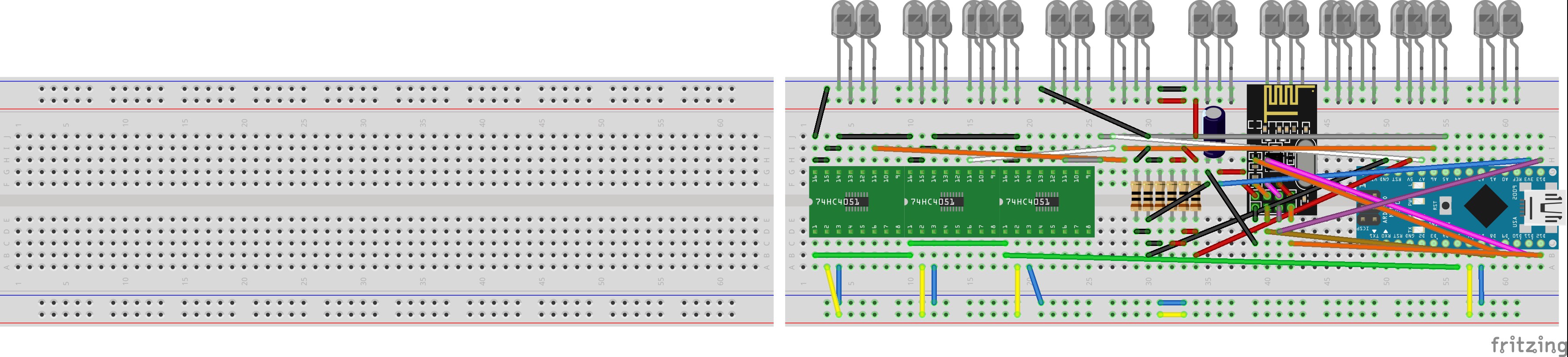


 Riccardo Pellegrini
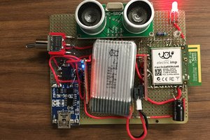
 Robert Ussery
 Robert L. Read