 kevinjkrieger
Brain: I needed something capable but not overkill, and I needed to be able to hand solder it. I had an old LPC1343 LPCXpresso board from a school project - so I thought to check on the LPC line of microcontrollers. Sure enough they have several with CAN bus options! The LPC11C14 is simple and has CAN circuitry built-in.
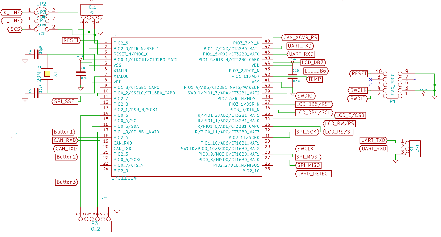
Here we can see the connections that the LPC11C14 has, including the programming/debugging header that attaches to the LPC-Link board. I broke out the UART pins because you never know if you'll need them.
A 20MHz crystal was chosen in order to be in the range required for CAN bus operation.
Solder jumpers enable me to choose to expose the microcontroller to the 3 other lines on my Honda Civic's OBD2 port - The "K-LINE", the "L-LINE" and "SCS". I have no idea what they are but you never know when you might need them.
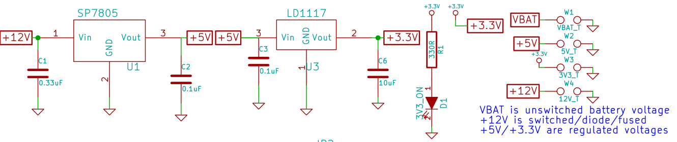
Here we have the power supply section. +12V on the left is from the Car's battery and is unswitched. Two linear regulators provide +5 and +3.3V. Initially +5V was only required for the CAN transciever, but I decided to use it to power the LM335 temperature sensor, as well as optionally the LCD screen. Test points also help with debugging, along with an always on LED.
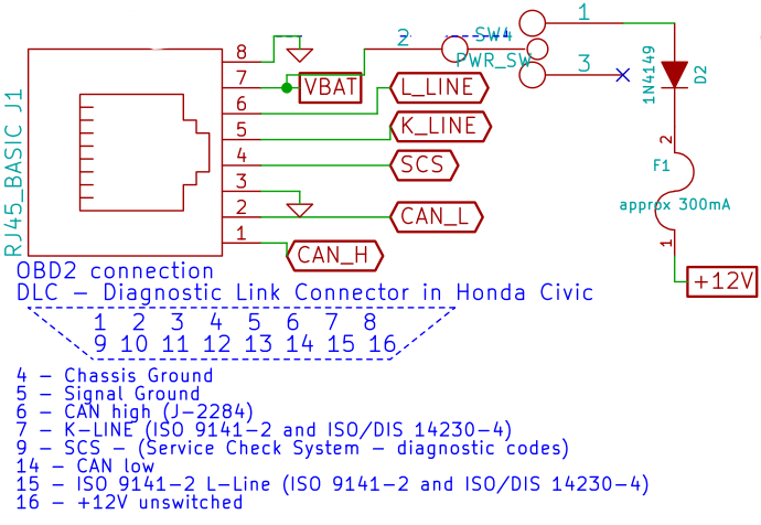
Here's the good part: The connection to the vehicle. I found the DLC information on the 'net and sort-of confirmed it by probing for +12V and the two ground points with a multimeter.
I chose RJ45 for the connector because I believe that ethernet cable is readily available, noise-resistant, can handle power (what is it, like 24AWG?) and otherwise easy to work with.
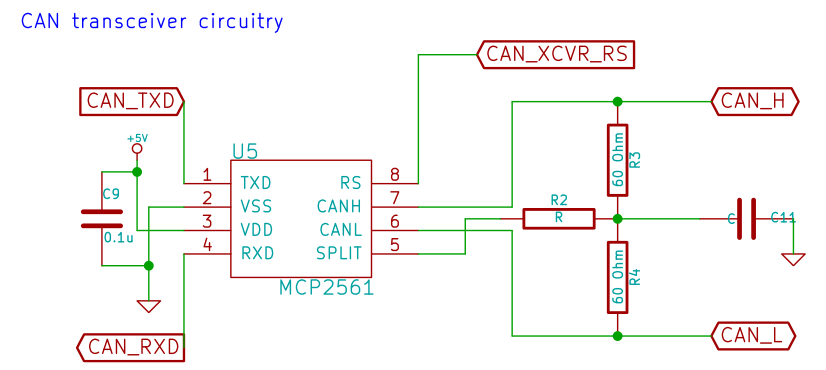
Here is the CAN transceiver. Small and simple. The circuit is based on the datasheet for the MCP2561. The signal "CAN_XCVR_RS" is connected to the microcontroller's GPIO and is used to enable/disable the transceiver.
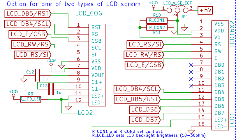 Here we have options! Variety is wonderful isn't it? The LCD_COG is the NHD‐C0216CZ‐NSW‐BBW‐3V3. It looks attractive and has a smaller footprint than the standard HD44780 types that you see everywhere. I didn't want to rely on the NHD LCD screen becase it is more expensive, so I also added in a footprint for the HD44780 LCDS. As a rule I don't like using pots, so for the contrast I have just added two resistors in a divider configuration. A pot can be added in debugging, a voltage determined and then resistors can be used. The voltage can be set to either 3.3V or 5V via a jumper, since there are so many different types available.
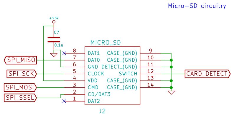
Here we go - storage, that is one of the goals of this project. Here is the microSD circuitry. Nothing special - the SPI port is being used as well as another GPIO pin for card detect (specific to the socket I'm using - it grounds a pin when a card is inserted, and it is left floating otherwise so a pullup is required). The socket has since been obsoleted (I got an email from digikey) so I guess I'll have to find another socket that I can hand solder :/.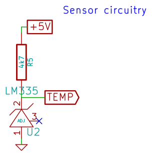
It's always nice to know your microcontroller is working properly. A temperature sensor (LM335) is added to have something to debug with. If I place my fingers around the sensor does the temperature rise? Indeed it does.
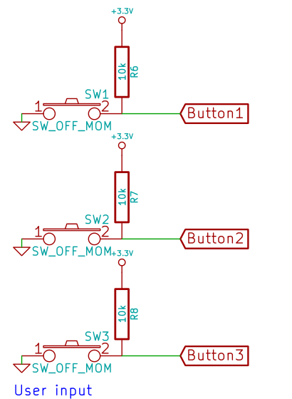
Lastly - we need to think about the user. How will he or she control this thing? Three buttons seems like a nice amount to have. They will probably control a state machine.