 kevinjkrieger
Yep mistake #3 already. Didn't think I could get off so easy. So I think we can all agree the goal of this whole project necessitates that the CAN transceiver works properly. I refer you to Mistake #1, let me quote: "always triple check your footprints." I guess I would need time travel to have listened to my own advise here.
Upon checking out the CAN transceiver to make sure it was outputting something when I was using the CAN module... I notice a little problem. I swapped one side of the footprint! Heh.
STDBY pin 8 was actually SPLIT pin5
CAN High pin 7 was actually CAN Low pin 6
CAN Low pin 6 was actually CAN High pin 7
SPLIT pin 5 was actually STDBY pin 8.
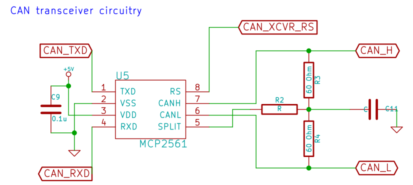
Oooops. What does this mean? Well - the two CAN pins are no problem, that just means I have to swap the wires in the cable that I made. How about the STDBY and SPLIT pins? currently I'm not using the SPLIT pin - since I don't have the R2, R3, R4 or C11 components in the following image populated I can just cut the trace connected to CAN_XCVR_RS and then bodge a wire from one of the spare GPIO to the one end of R2. It's fixable! On a side note: I would populate the three resistors and capacitor if my device was going to be one end of the CAN bus, but it is not, there are already two termination ends to the CAN bus in the Honda Civic's circuitry. Read the datasheet for the MCP2561 for details.
Oh BTW, the RS pin enables or disables the transceiver, so it's kinda important. That's all for now.
Discussions
Become a Hackaday.io Member
Create an account to leave a comment. Already have an account? Log In.