 Miroslav Zuzelka
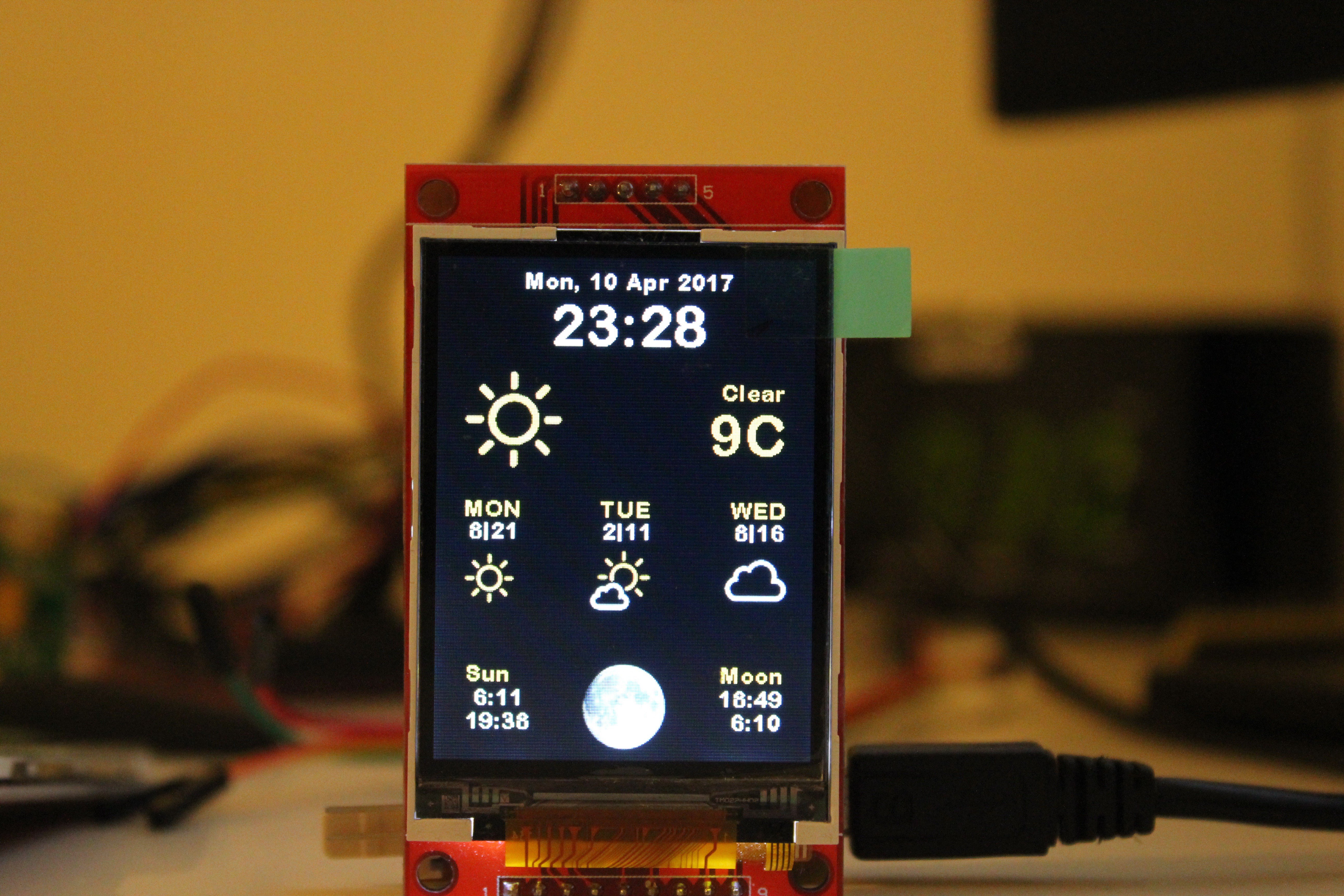
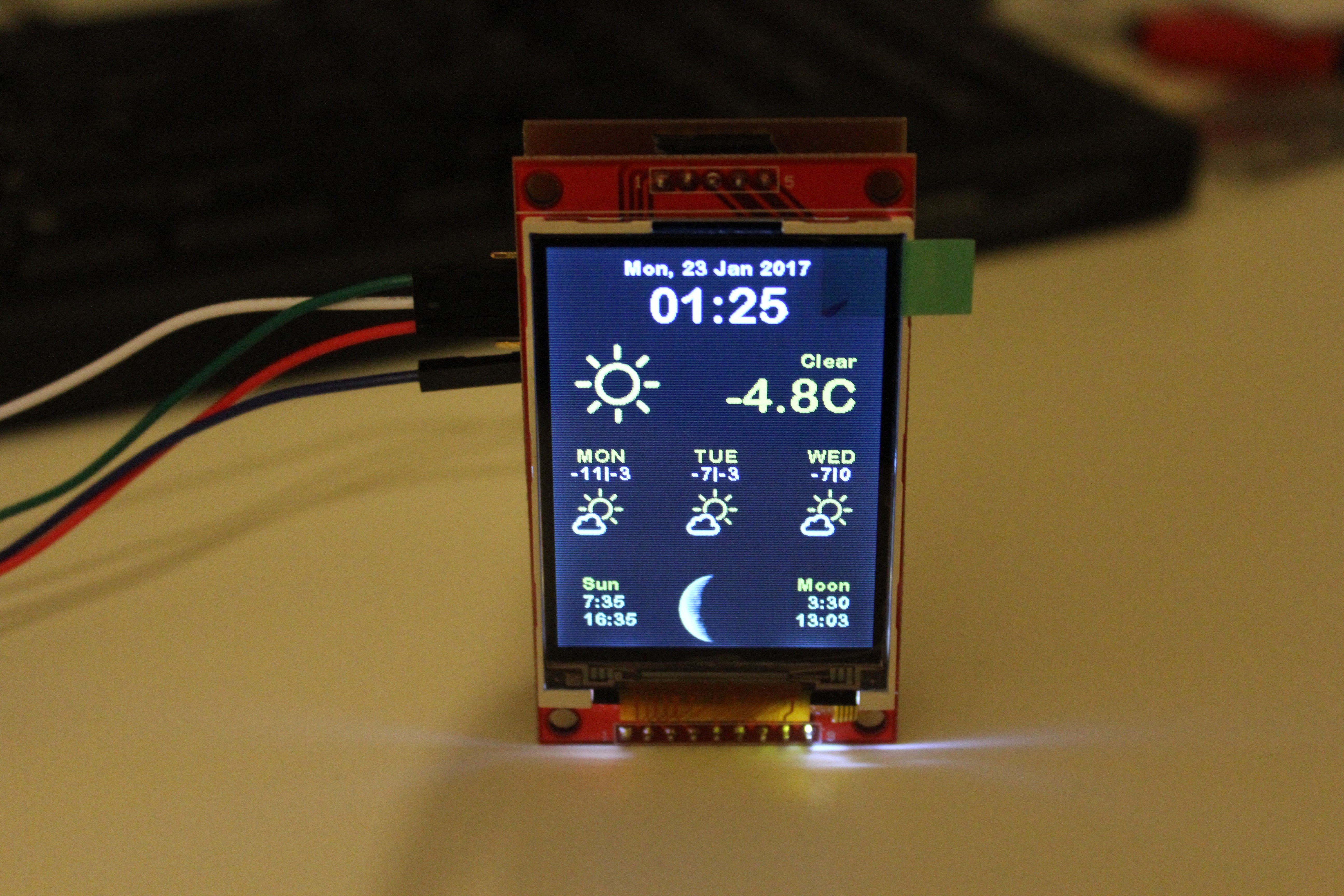
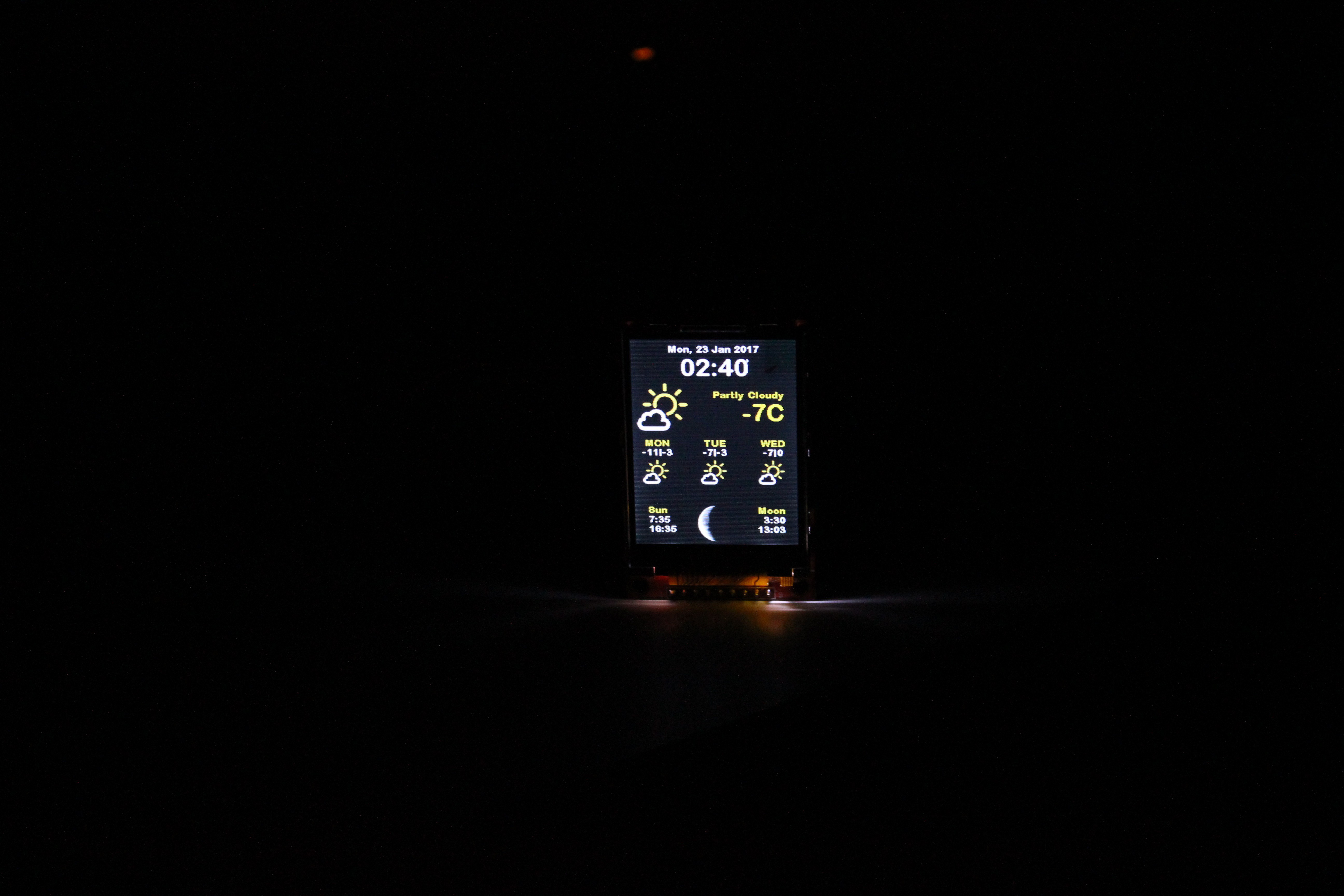
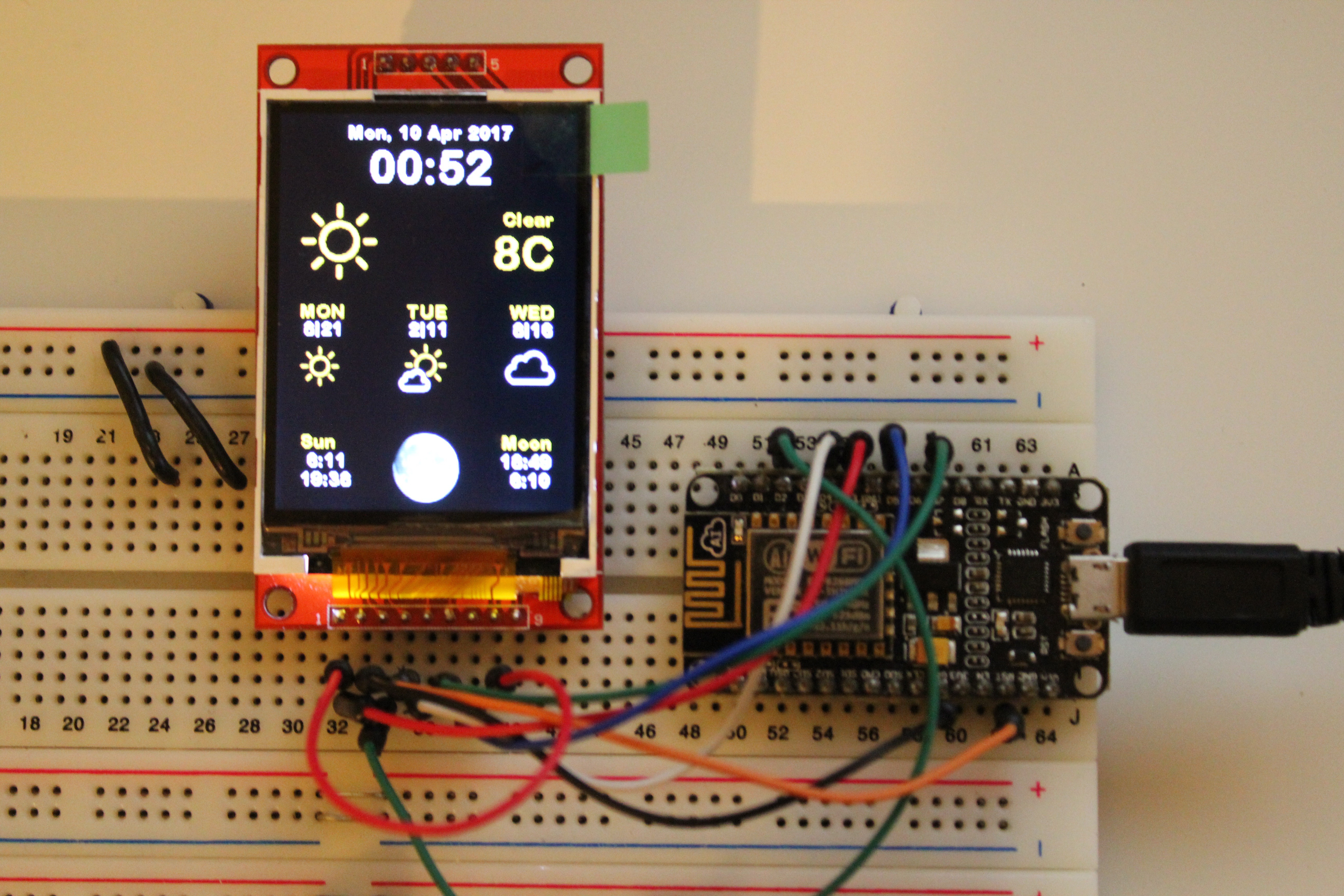
This is just DIY version of Weather Station by Ruiz Brothers with parts from comrades in China. I want to make board which will be brain of the weather station and also will have more features then original project. I can imagine few of these station around the house in every room, which will read temperature and humidity and store these values in local/internet database or it can communicate with central unit in the house and regulate heating in the room. That´s just an idea, what would you do with something like this?
0%
0%
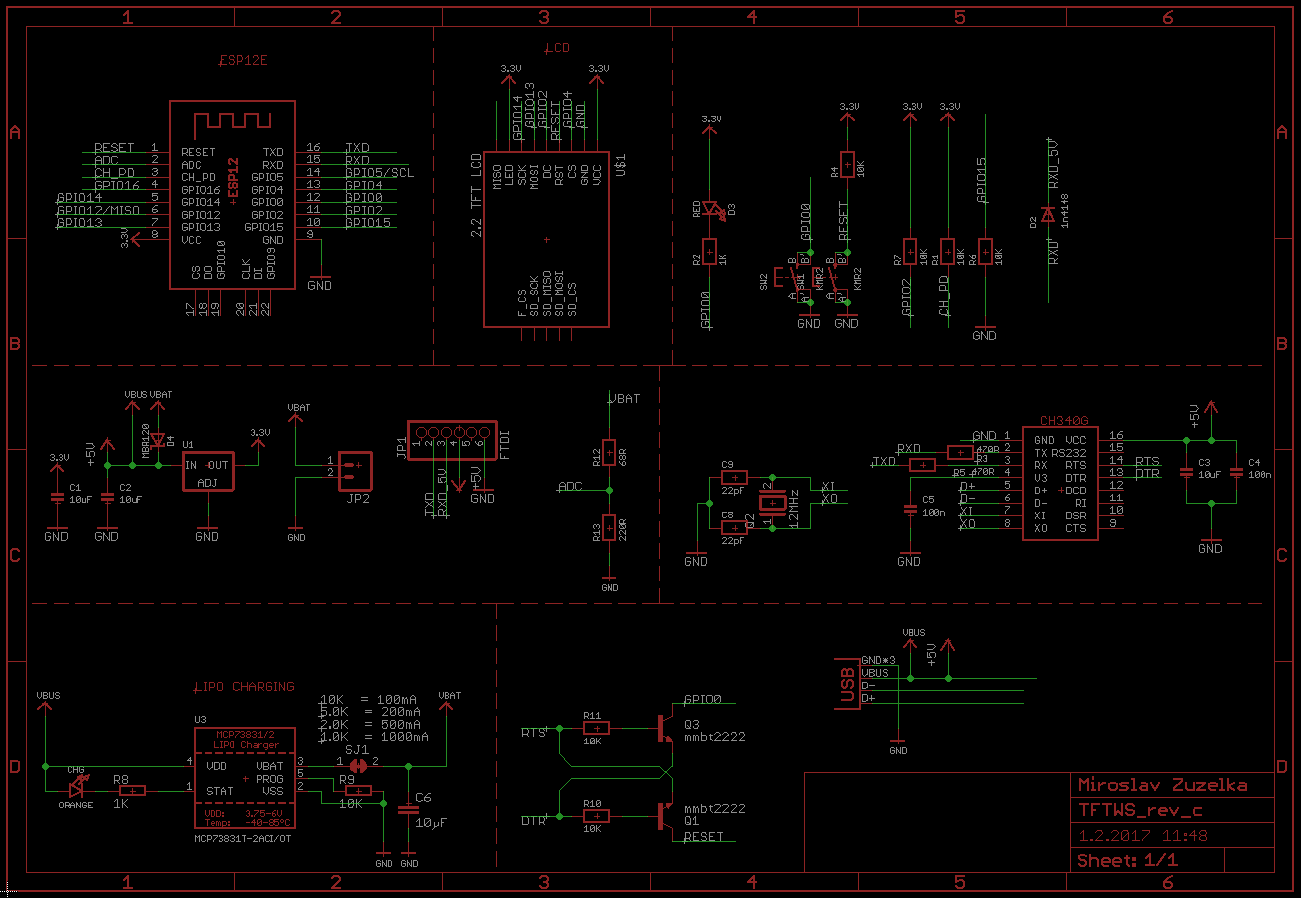
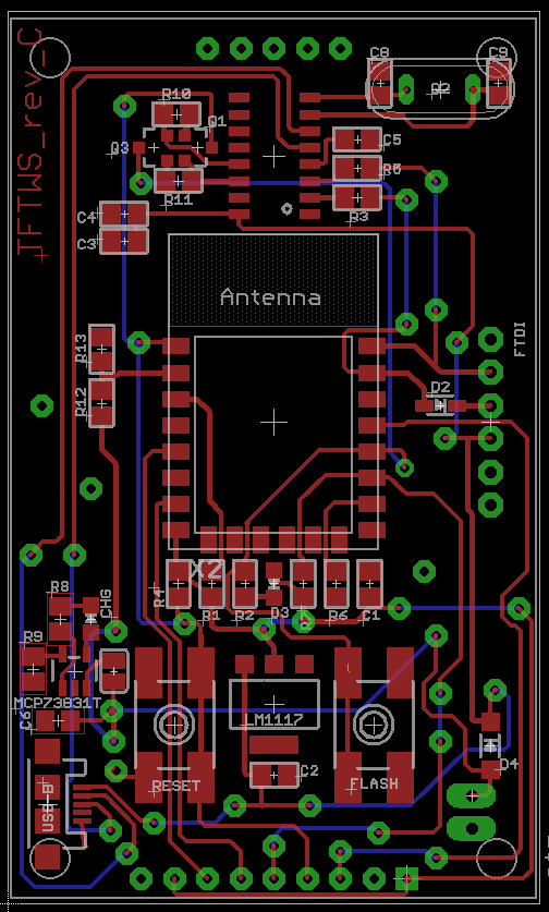
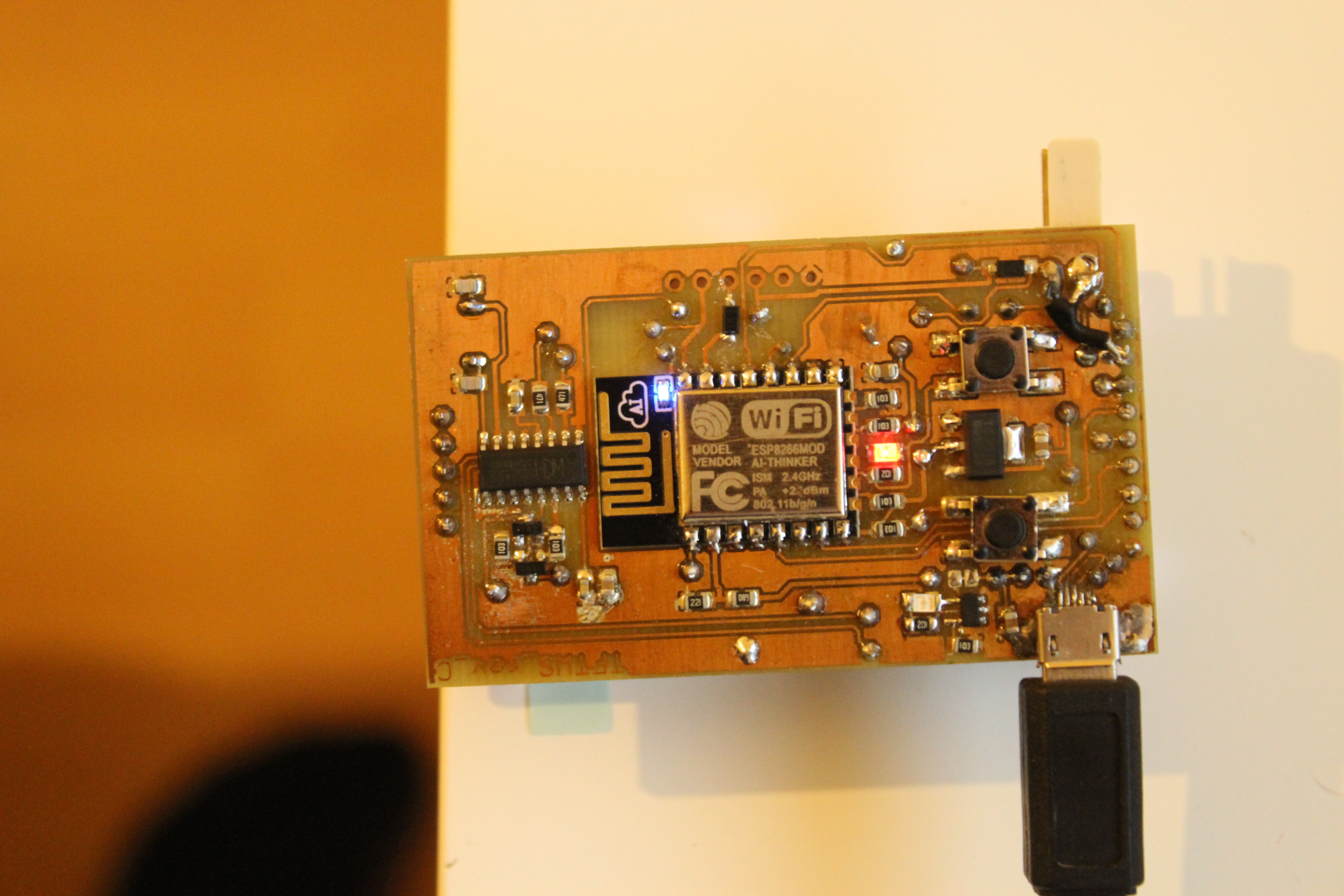
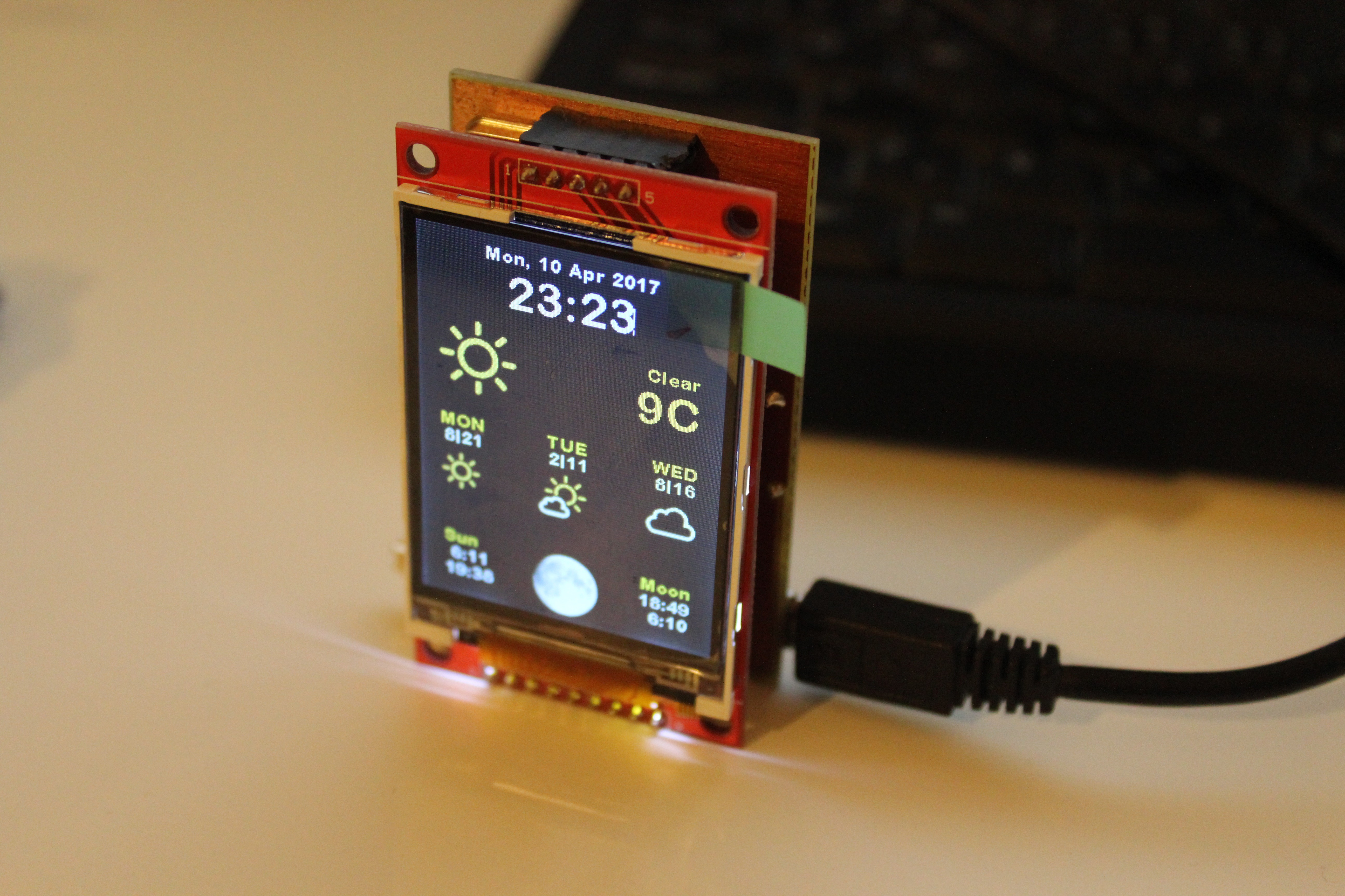
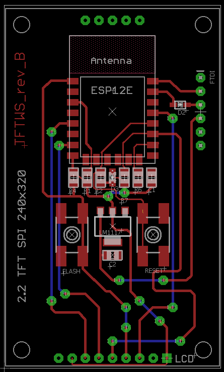
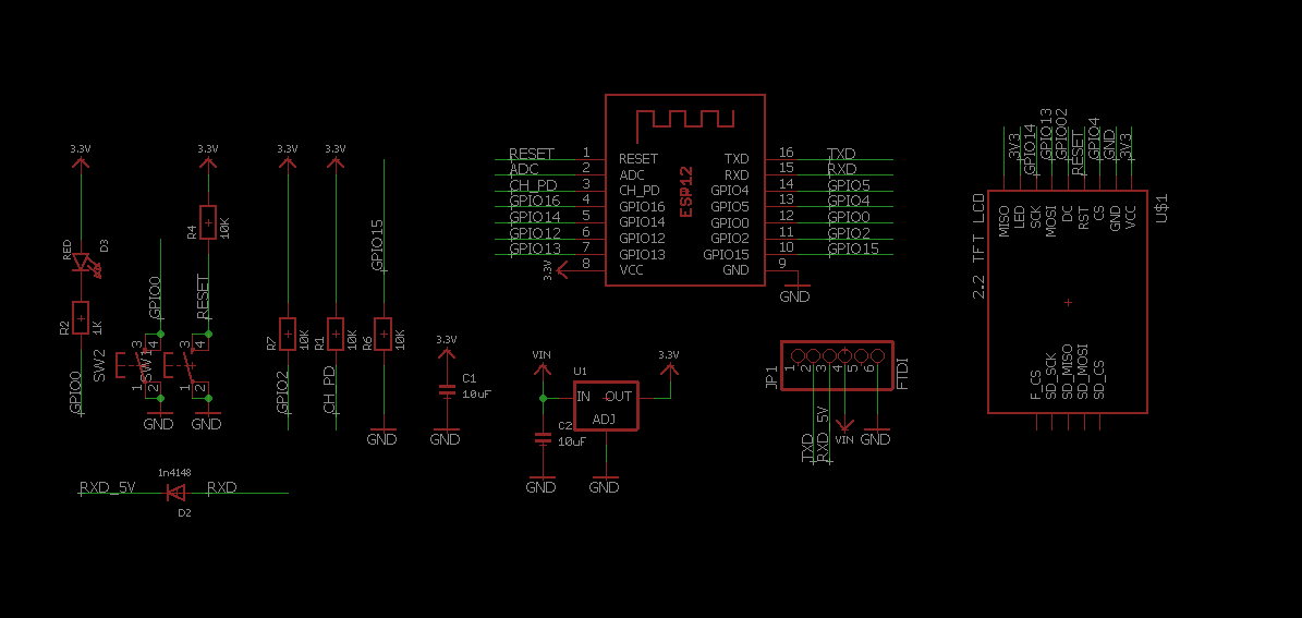
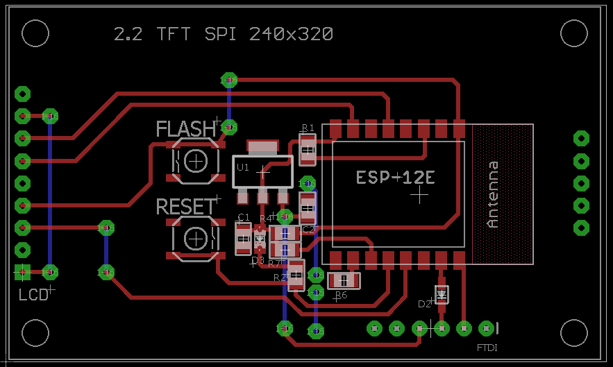
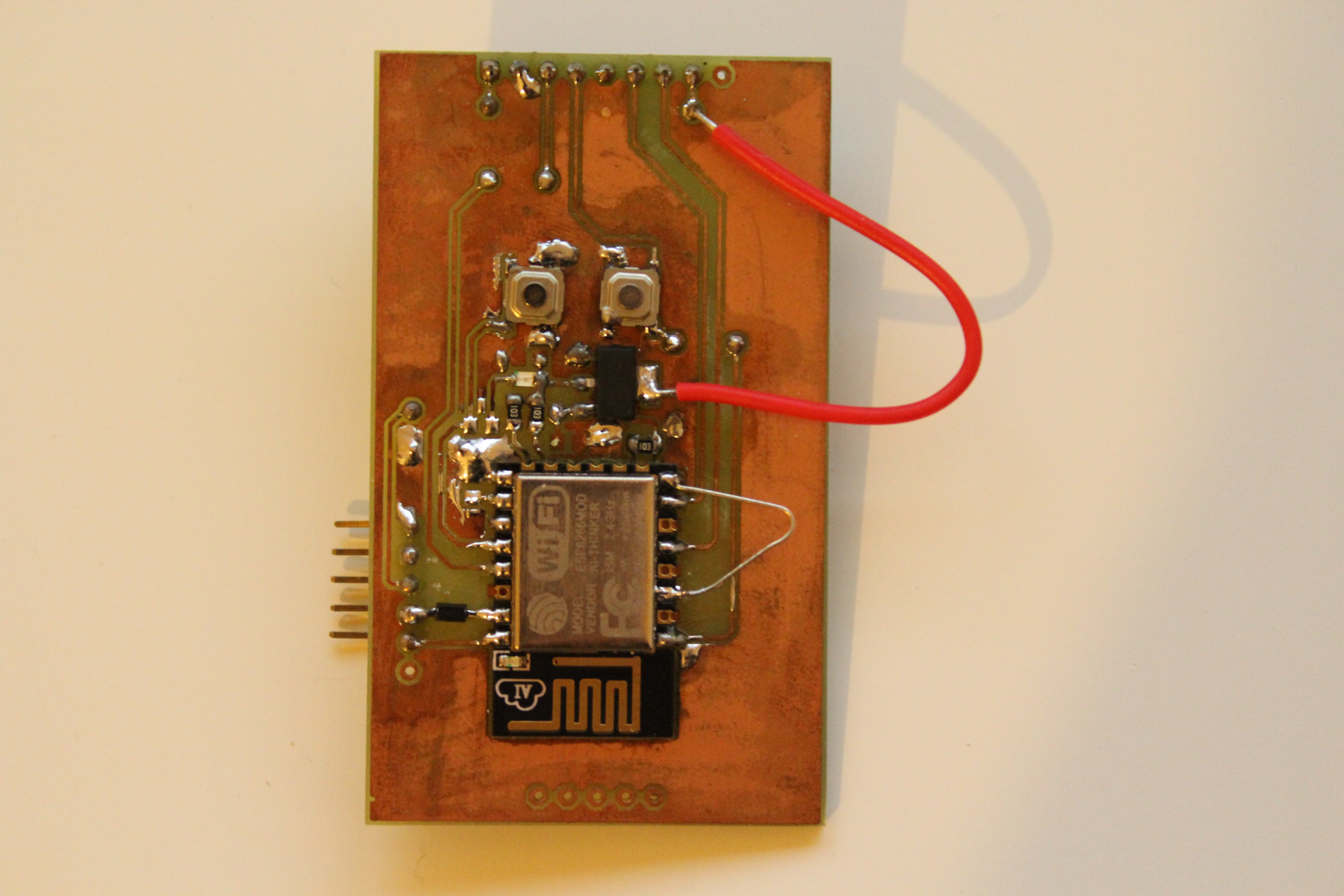
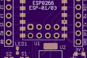
Weather Station PCB
DIY PCB for Weather Station
Become a Hackaday.io member
Already have an account? Log in.
Just one more thing
To make the experience fit your profile, pick a username and tell us what interests you.
Pick an awesome username
hackaday.io/
Your profile's URL: hackaday.io/username. Max 25 alphanumeric characters.
Pick a few interests
Projects that share your interests
People that share your interests


 drewrisinger
 Stefan Lochbrunner
 Chris
Chris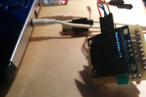
 Jakub Piasecki