 Dr. Cockroach
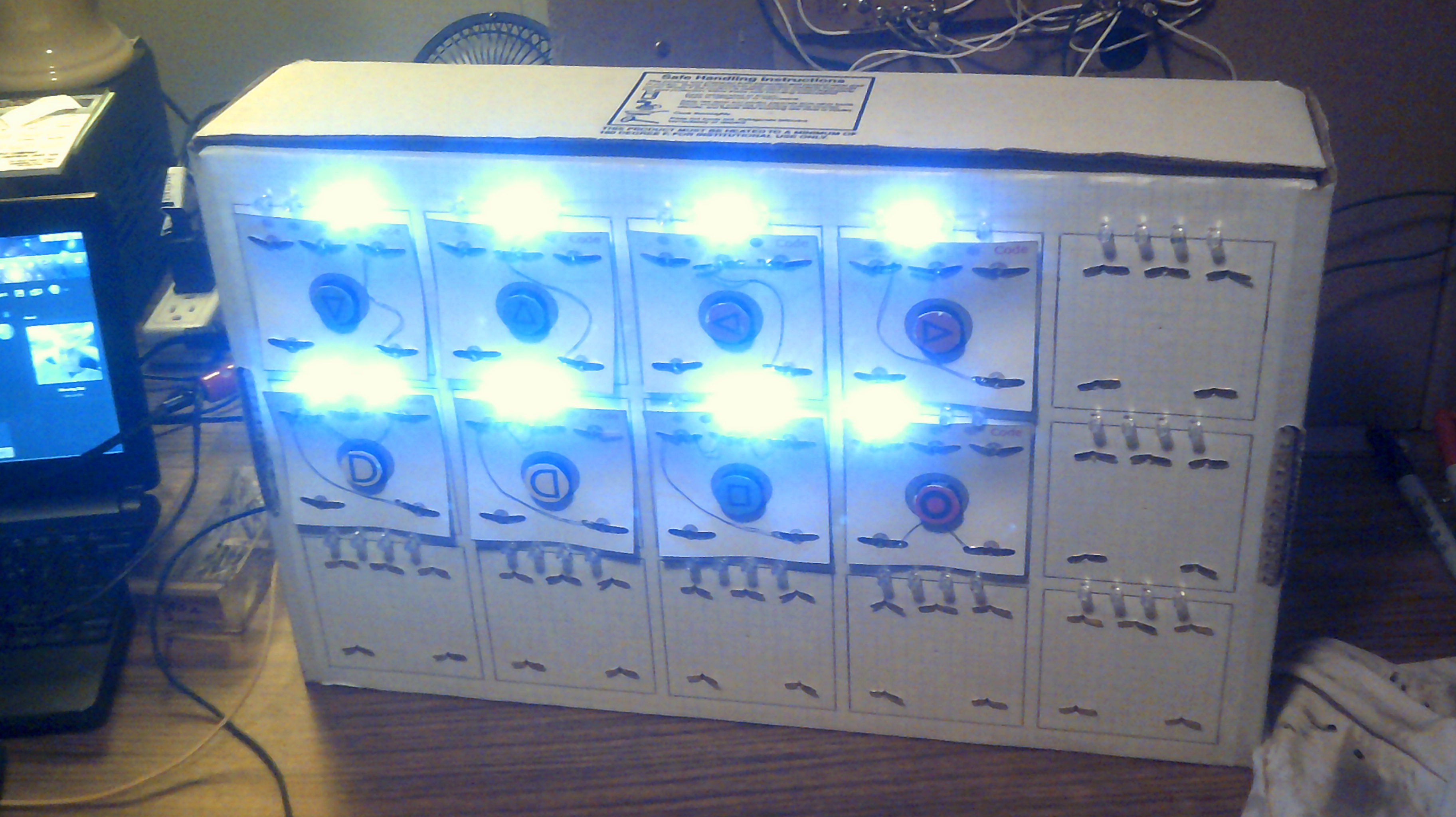
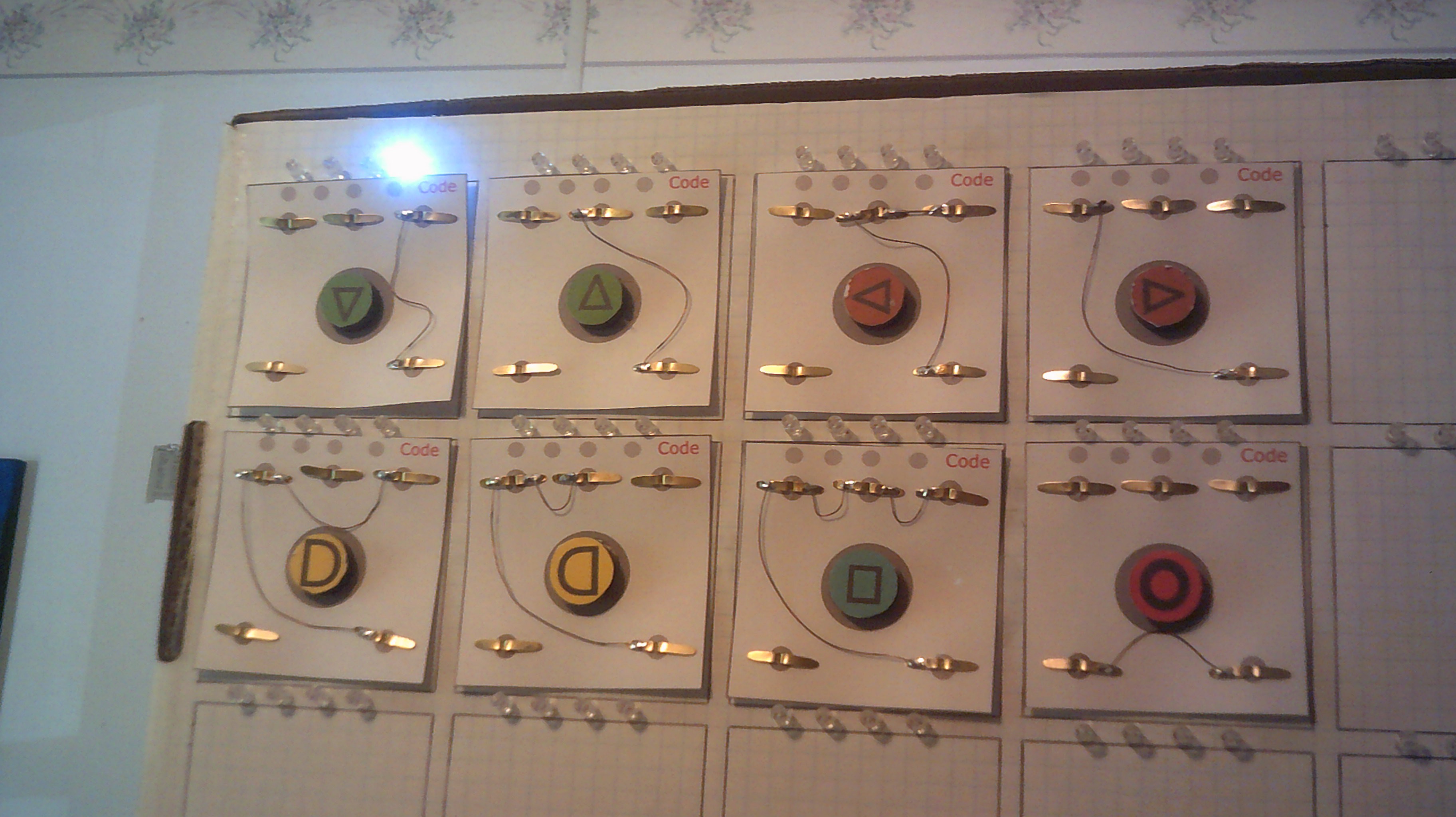
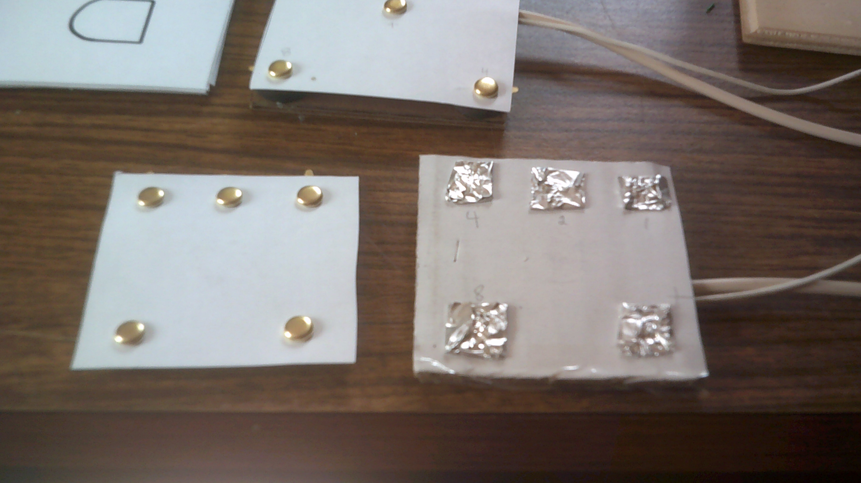
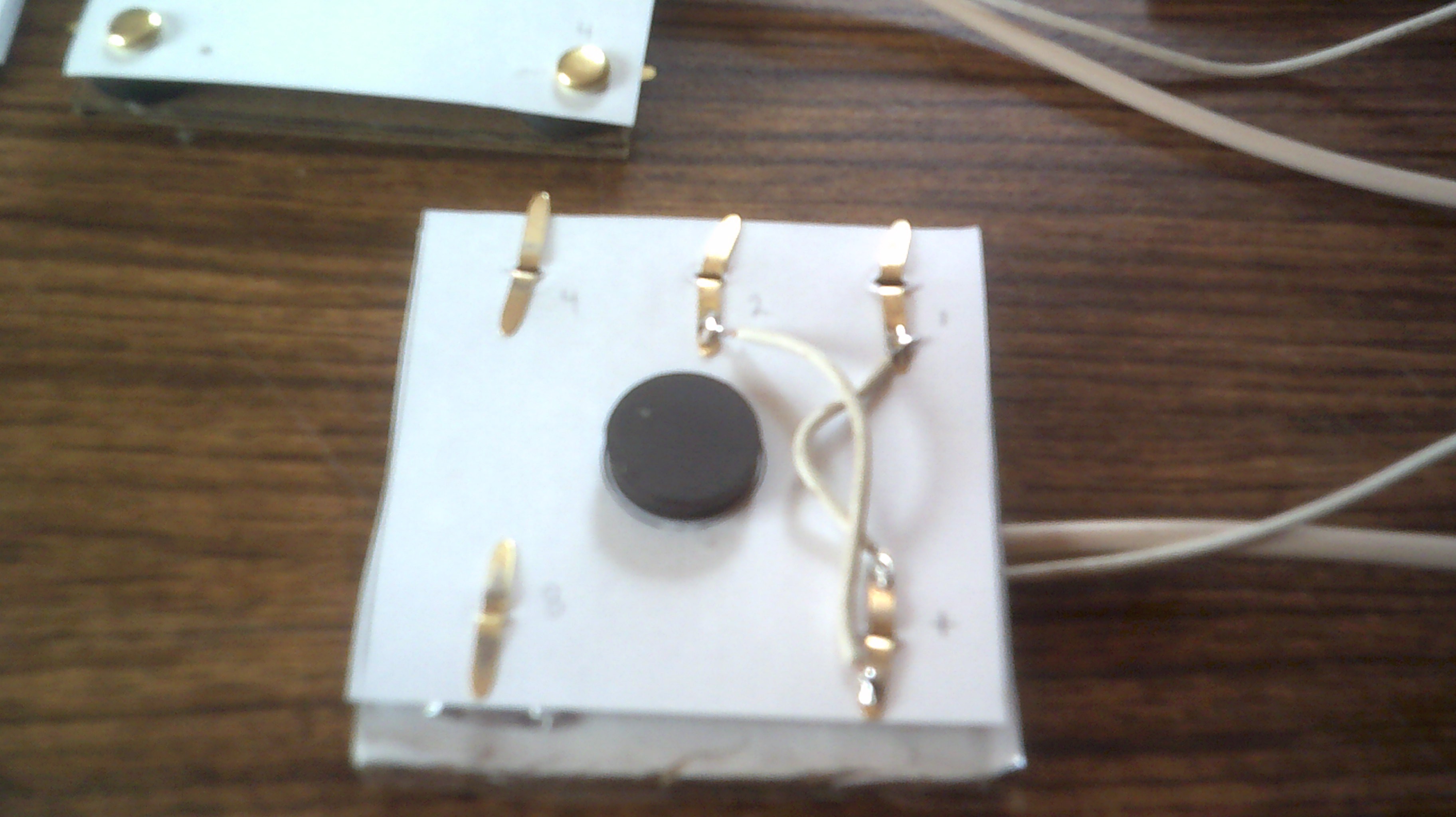
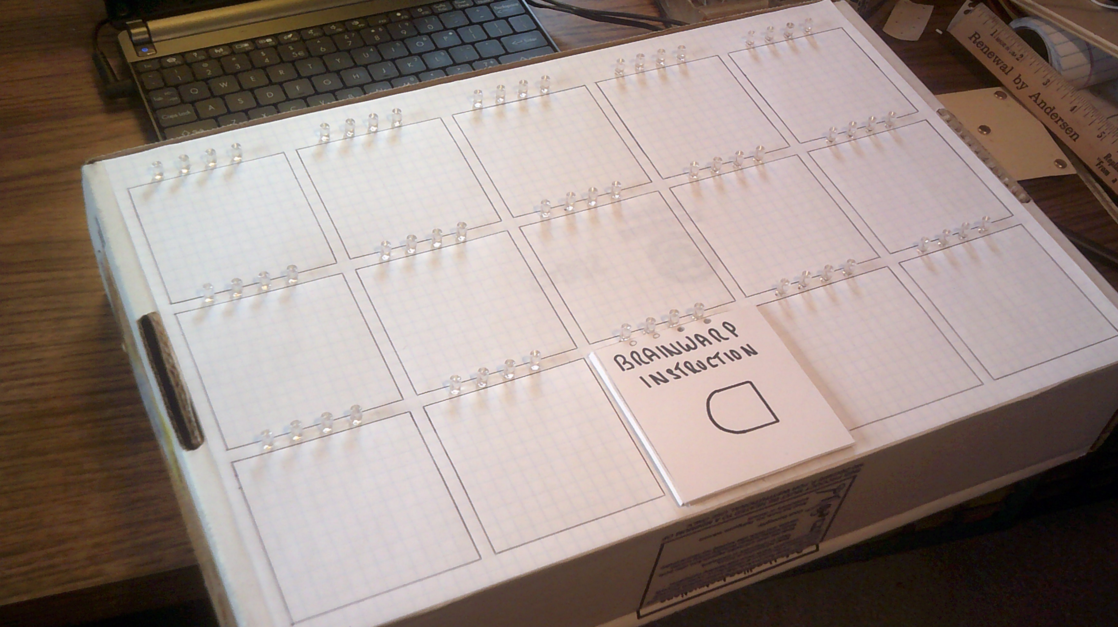
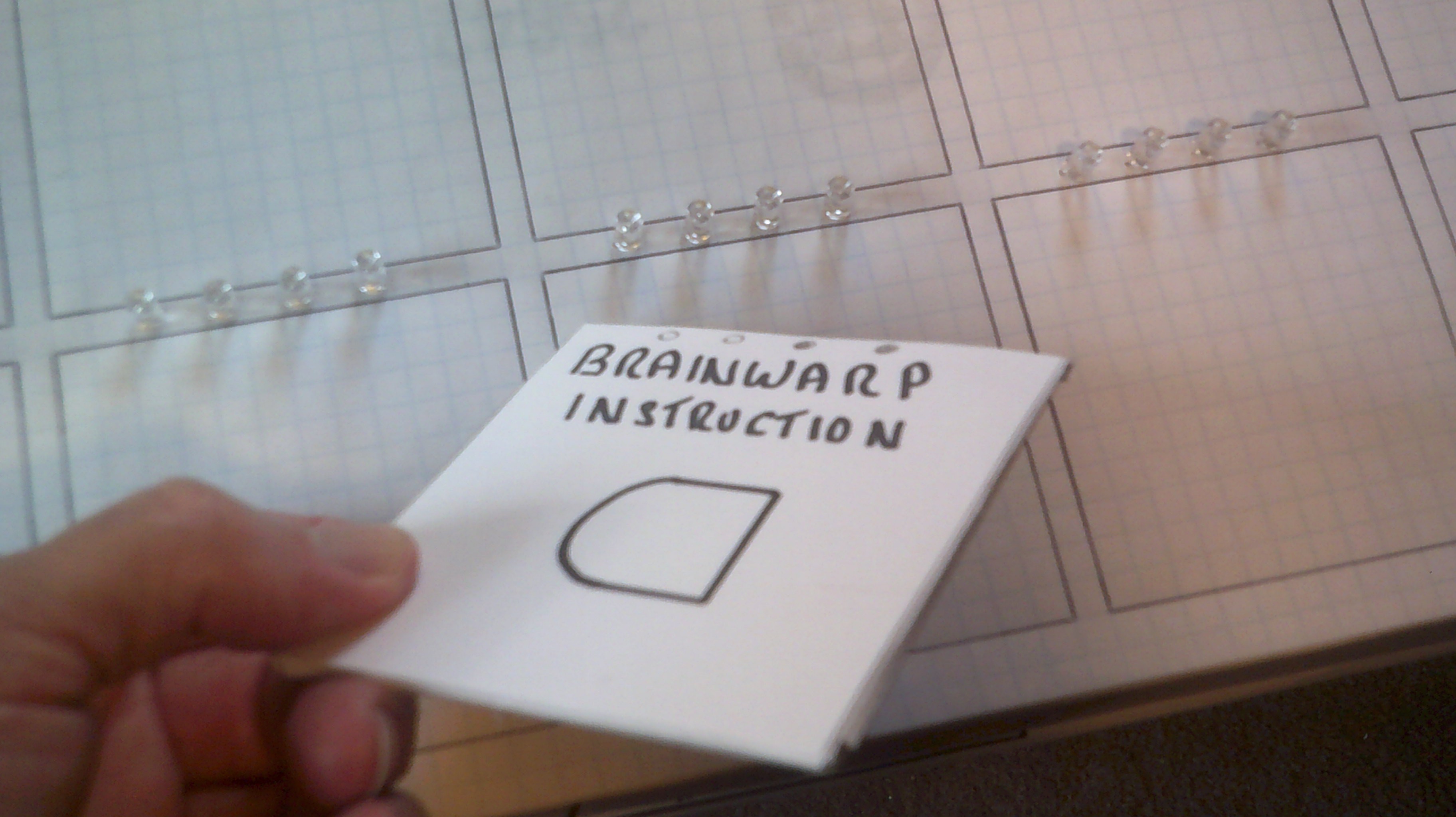
The Brainwarp program entry panel is constructed with 15 instruction entry pads each measuring about 3 by 3 inches and arranged in a 5 by 3 pattern. Each pad will have 4 leds mounted above that will indicate what instruction card has been placed on the pad. The pads act as EPROM in that they are wired and read as program memory.
The Brainwarp instruction set is very RISC. It is based on Brainf*ck or BF with some major changes. BF was intended to have 30,000 pointer cells where as Brainwarp will initially have 15. The small number is in keeping with the 4 bit system. This can be expanded later if desired. The data input and output for BF is ASCII where as Brainwarp is decimal / binary.
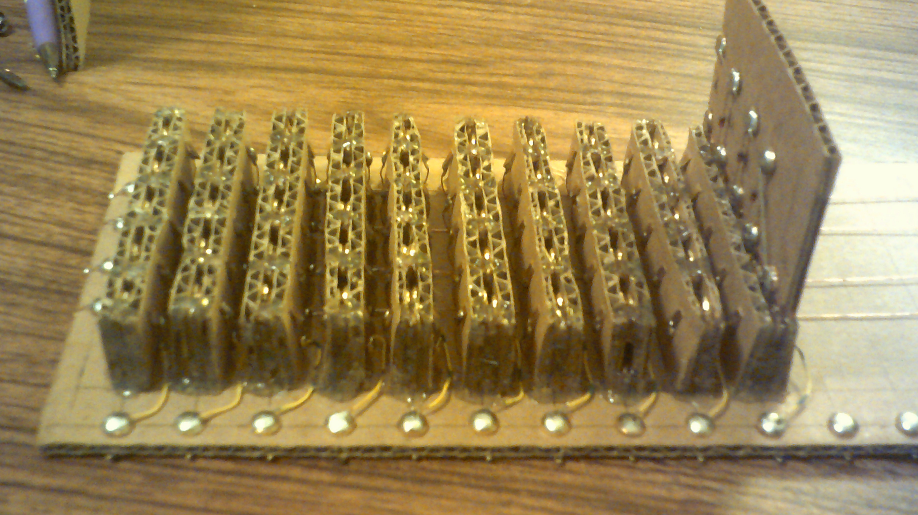
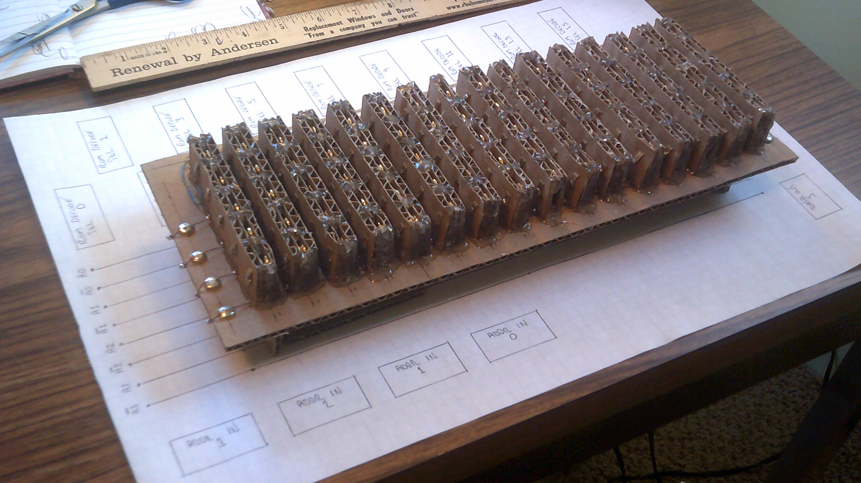
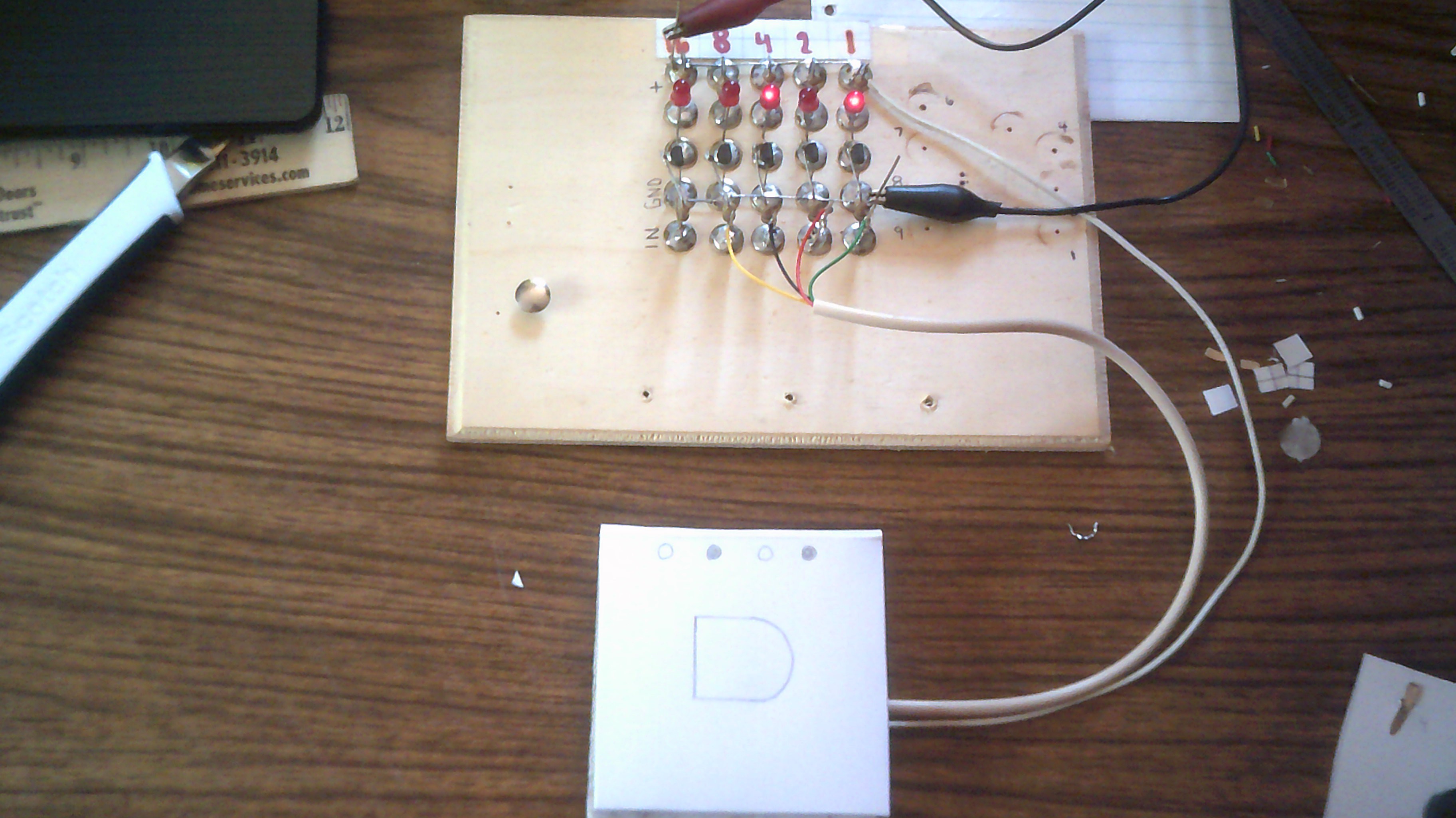
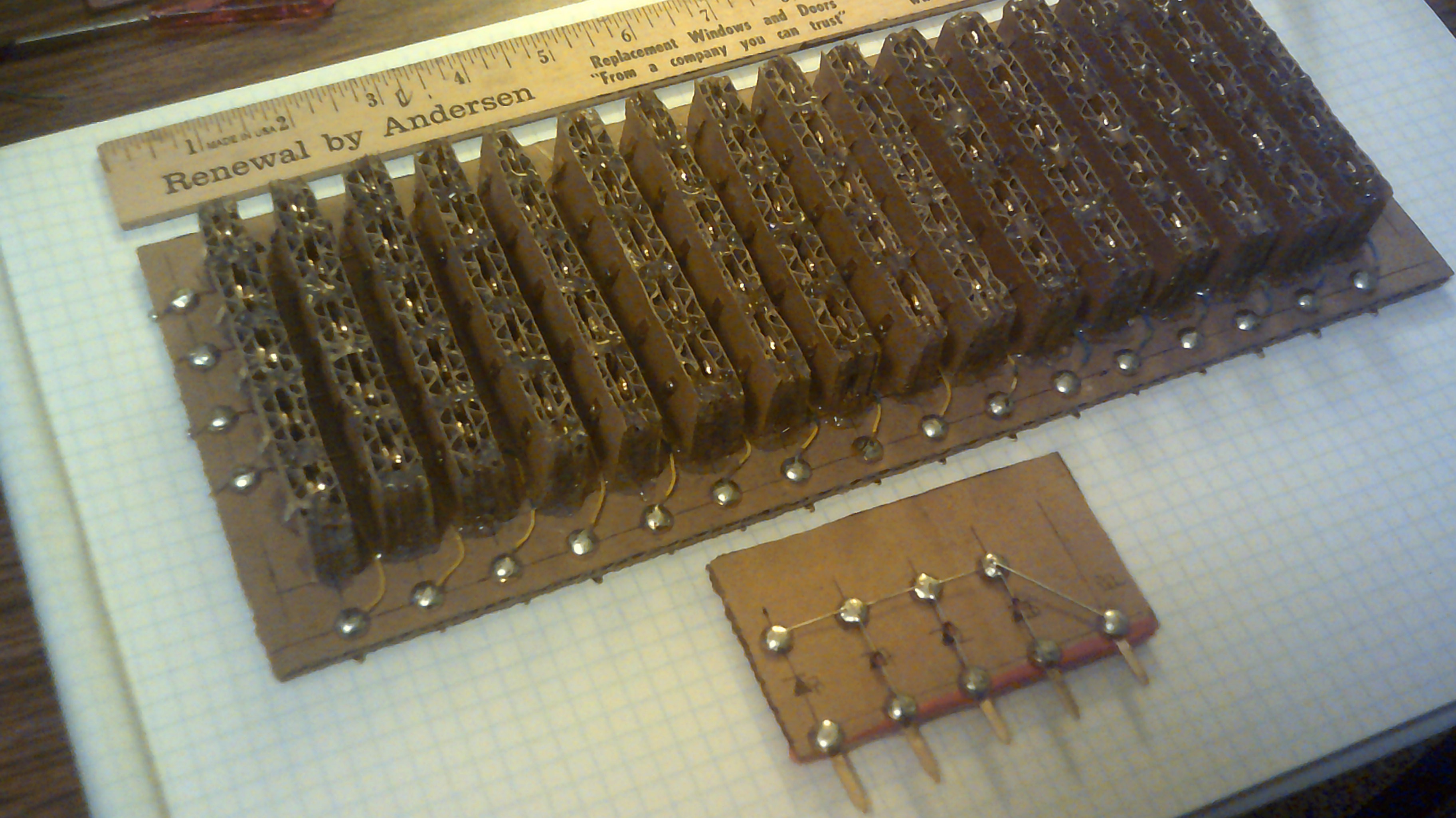 Here is the basic layout for the ROM logic board. The ROM back plane will mount above.
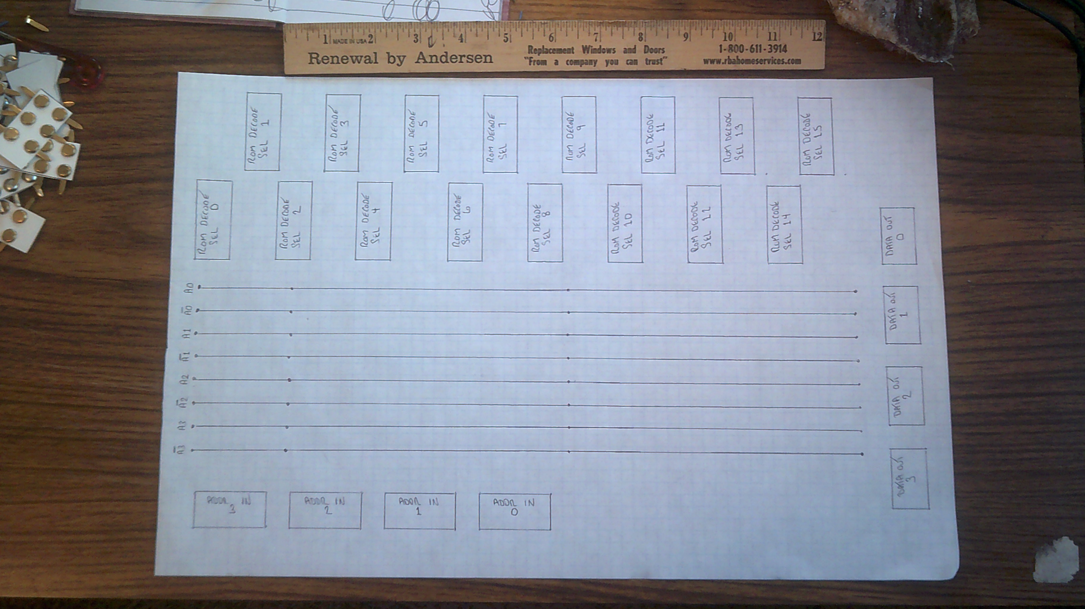


 land-boards.com
 Michael Wessel
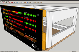
 Alexios C
That panel is looking better and better :-)