 Ted Yapo
I threw together a quick breakout for the fl2k dongle so I can hook it up with all the connectorized microwave junk I've accumulated over the years from ebay. There are min-loss pads on there for converting the 75-ohm output of the VGA channels to 50-ohms. You can populate them with jumpers if you don't care about matching and want to avoid the 5.72 dB loss.
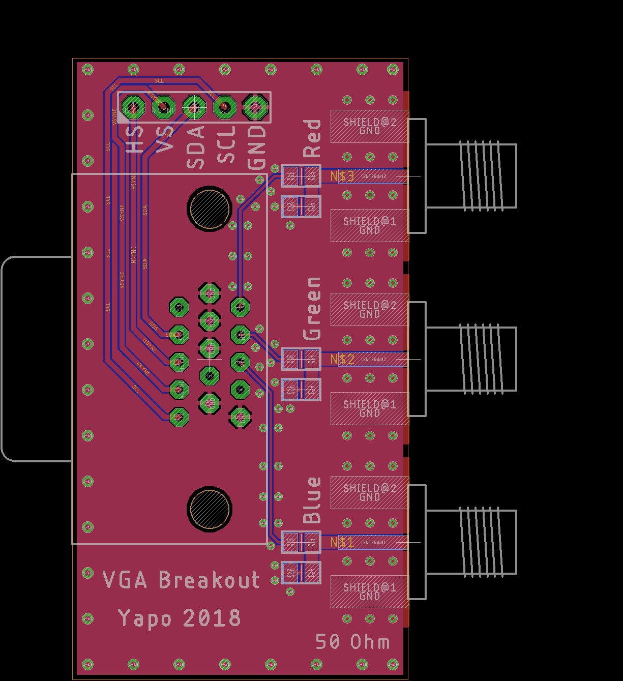
I also broke out the I2C lines and the horizontal and vertical sync for good measure. This PCB should make quick experiments easier. I'm putting the design in GitHub, but not sharing it on OSH Park yet because I haven't tested the VGA connector footprint. Once it checks out, I'll share the design and post a BOM.
The 75-ohm traces taste like 75-ohms, and the 50-ohm traces taste like 50-ohms, at least according to AppCAD.
The osmo-fl2k code seems to just use the red channel at this point, but I can imagine using two of them for I/Q outputs, which would be pretty cool. Maybe you can even do some primitive beam forming with just three outputs?
Here's the schematic:
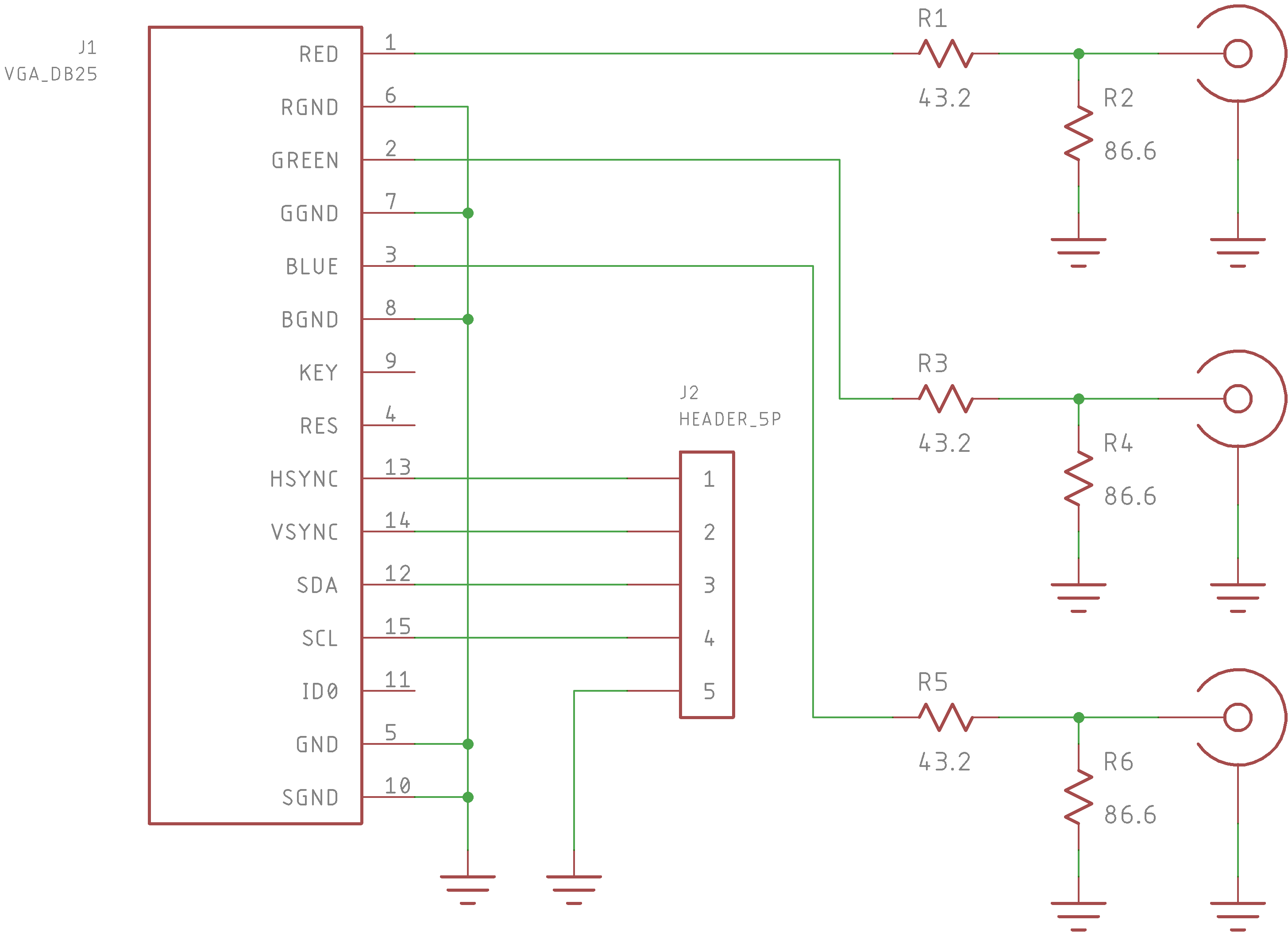
It's really embarrassingly simple.
I cribbed the matching pad design from this Maxim app note. I used to enjoy working through the algebra for those kinds of things, but lately I don't feel like spending the time.
I also sent out a lowpass filter design, which I'll write up in a separate log.
Discussions
Become a Hackaday.io Member
Create an account to leave a comment. Already have an account? Log In.
totes buying one and now I dont need to do mine ;)
Are you sure? yes | no
If you feel lucky, there's an OSH Park-ready zip file of gerbers in GitHub. I'm not sure the VGA connector will fit yet, though. I just drew the footprint last night. I haven't messed one up too badly in a while, though :-)
Are you sure? yes | no
That VGA connector looks kinda odd. The part I use have plated holes and work nicely with solder down tabs or screws. The pad is set for proper mounting hardware clearance.
You have non-plated through mounting hole, so you would need clearance for screw head/nuts 4-40 or M3. I would certain put more clearance around the mounting hole. That "Red" track is a bit close to the hole.
Are you sure? yes | no
@K.C. Lee They're snap-in tabs. I hadn't considered that I should be soldering them. A plated-though hole is probably a better idea anyway.
https://www.digikey.com/products/en?keywords=609-4022-ND
I'll re-spin the PCB for anyone who wants to have them made (after I check everything else). Adding more clearance to the red channel is a good idea. On the first batch I can rework them to solder the tabs by scraping away some soldermask and bending the tabs backwards flat with the PCB. Ugly, but probably doable.
Are you sure? yes | no
That looks like the type on my FPGA card. I have no idea where my connector footprint came from as its name doesn't match anywhere else in Eagle libraries.
Likely you can do without the mounting holes unless you have a heavy cable, but it is one of those things I would fix now and not have to worry again.
Are you sure? yes | no