 Ted Yapo
The PCBs for the breakout board and lowpass filter arrived yesterday.
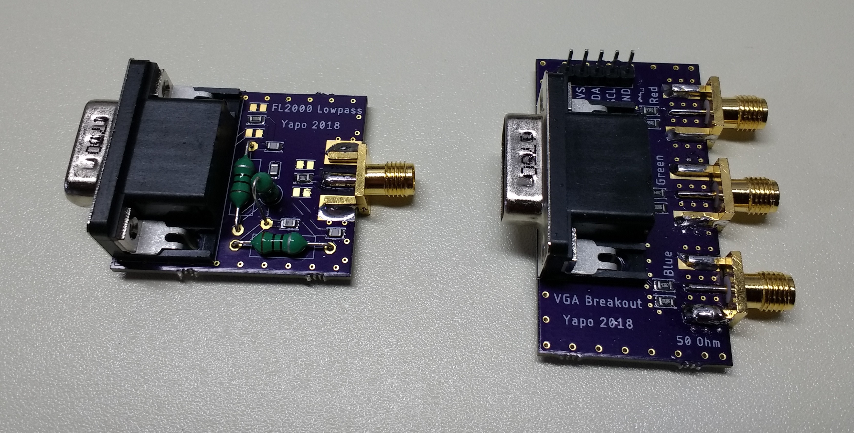
The VGA connector fit, but the holes don't leave much room for tolerances. I updated the PCBs in the GitHub repo with the hole sizes recommended on the datasheet, although they seem a bit big to me: tolerances will not be an issue :-). I also added plated-though holes for the VGA connector snap-in tabs so they can be soldered down for a more secure mounting (thanks @K.C. Lee). On the prototype PCBs, I scraped away some of the soldermask near the outer tabs to solder them. It's not electrically necessary, but adds some extra mechanical strength.
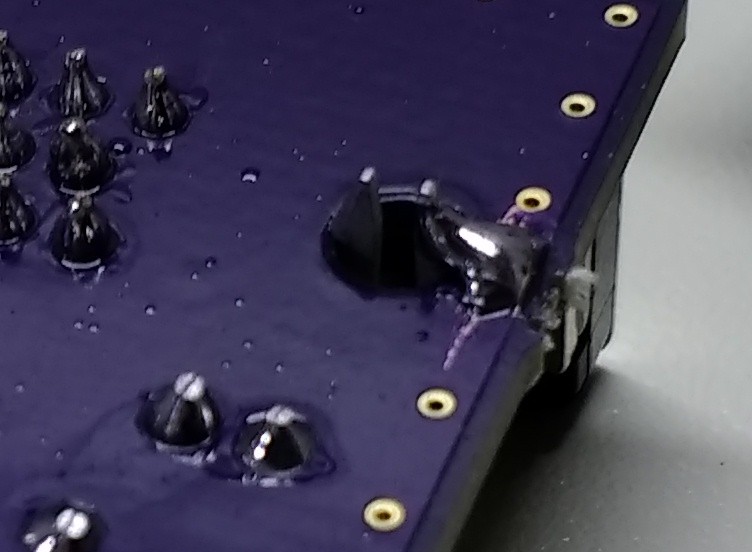
In between designing these two PCBs, I drew a new footprint for the edge-launch SMA connector for better impedance matching, but forgot to remove the soldermask on the bottom layer so the bottom tabs of the connector could be soldered.
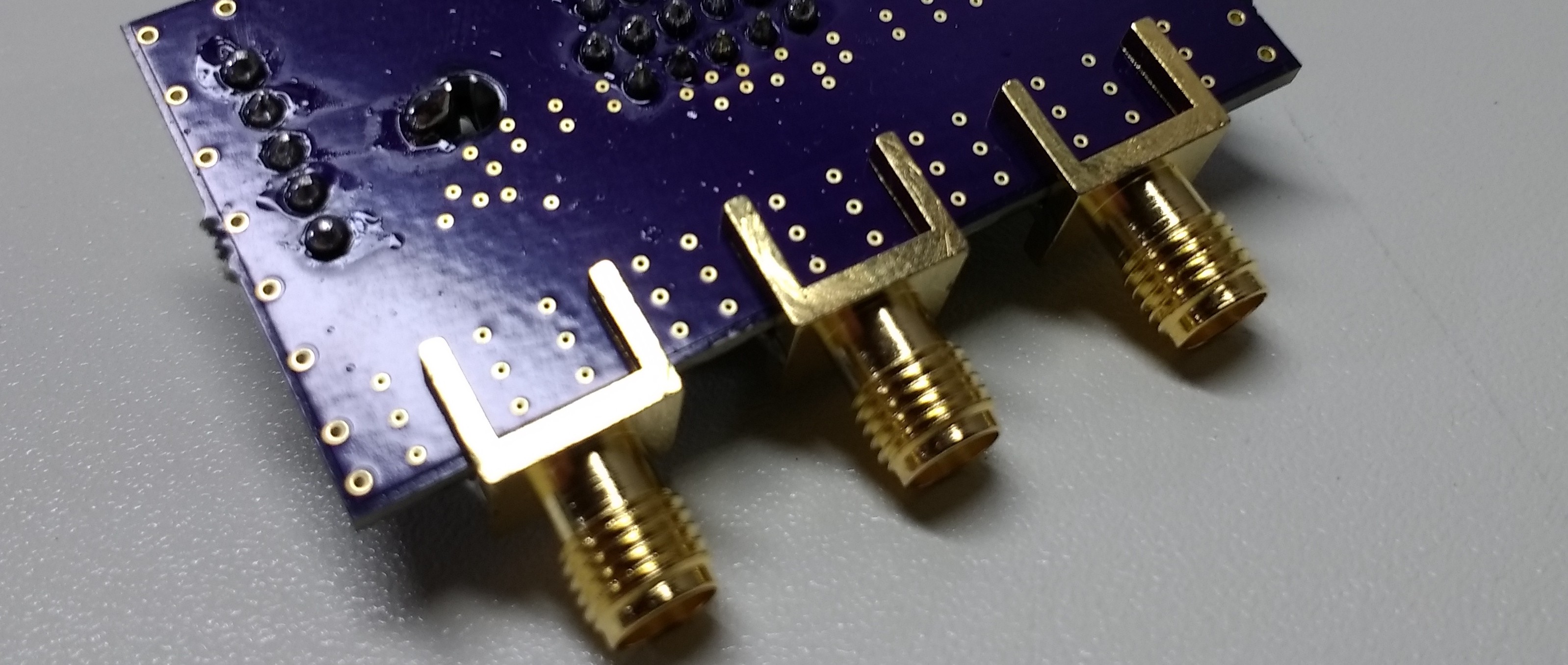
There are generous vias in the footprints, with ground planes top and bottom, so it's more of a mechanical thing at least for the frequencies I'm worried about at the moment, and these are fine for prototypes. But, if you are going to make some of these PCBs, grab the latest from GitHub (or the OSH Park links below), since I did fix this after ordering the boards.
I also reduced the size of the breakout so the longest dimension is less than 50mm, which might matter if you order PCBs from somewhere else.
Details about each board, including BOMs and test results are shown below.
VGA Breakout
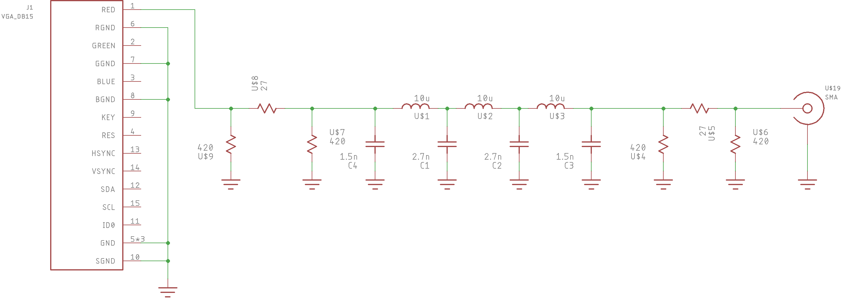
I discussed the breakout in a previous log. Here's the schematic again for reference:
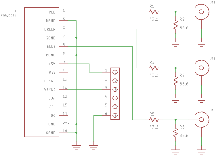
The resistor networks match the 75-ohm VGA outputs to the 50-ohm SMA connectors. You incur almost 6dB of loss for this, so if you don't care about matching, you can just use zero-ohm 0805 jumpers at R1, R3, and R5, and not populate R2, R4 and R6.
PCBs can be ordered from OSH Park.
You also need these parts:
- (1x) Amphenol VGA Connector, MFG# 10090926-P154XL, DigiKey# 609-4022-ND.
- (3x) Yageo 0805 86.6 ohm resistor, MFG# RC0805FR-0786R6L, DigiKey# 311-86.6CRCT-ND
- (3x) Yageo 0805 43.2 ohm resistor, MFG# RC0805FR-0743R2L, DigiKey# 311-43.2CRCT-ND
The header is just a standard 5-pin 2.54mm spaced header. I ordered 9mm wide (not the narrow 6.5mm) SMA connectors from ebay - make sure you get ones that match your PCB thickness (typically 1.6mm from OSH Park). You only need one for now, because the osmo-fl2k code only uses the red channel, but should it be expanded to use green and blue, you may need all three.
AM LPF
I designed a lowpass filter for the AM broadcast band. Obviously, it's your responsibility to obey the regulations regarding RF emissions wherever you are, but this might help you stay out of trouble. At least in the US, you are allowed to operate very-low powered transmitters in the AM broadcast band (I'll leave locating and interpreting the regulations as an exercise for the reader). What could easily get you into trouble, though, is any emissions in the amateur HF allocations. Amateur radio operators guard their spectrum like a dog with a bone, and will find you and harass you at the slightest provocation. This filter will kill harmonics that might interfere with the ham bands.
Here's the final version of the lowpass filter as simulated in LTspice:
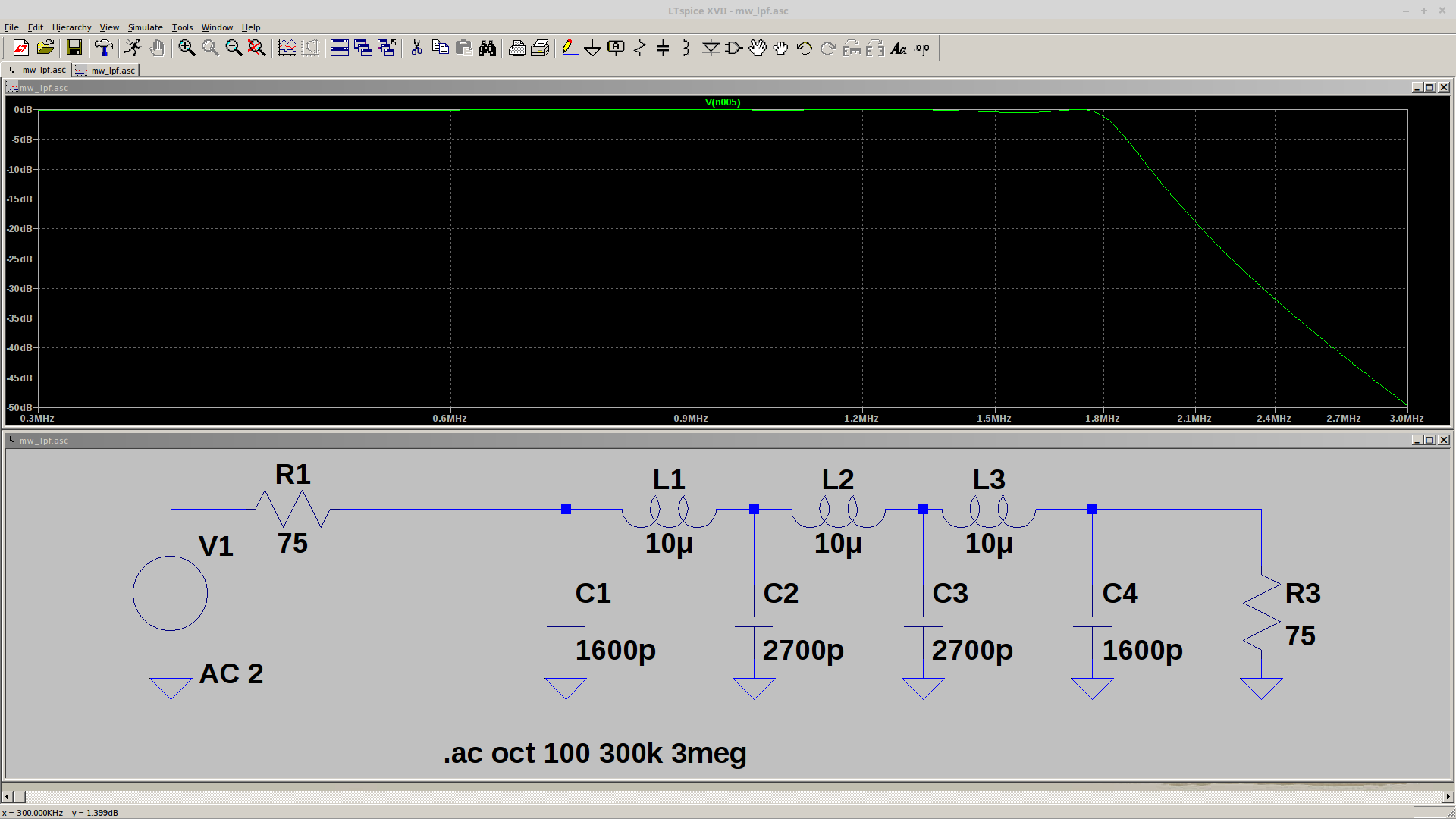
The original design had 9.1uH inductors at L1 and L3, but I substituted 10uH because high-Q ones with a decent SRF were available. The passband extends to around 1.8MHz, then drops off quickly. See below for some test data.
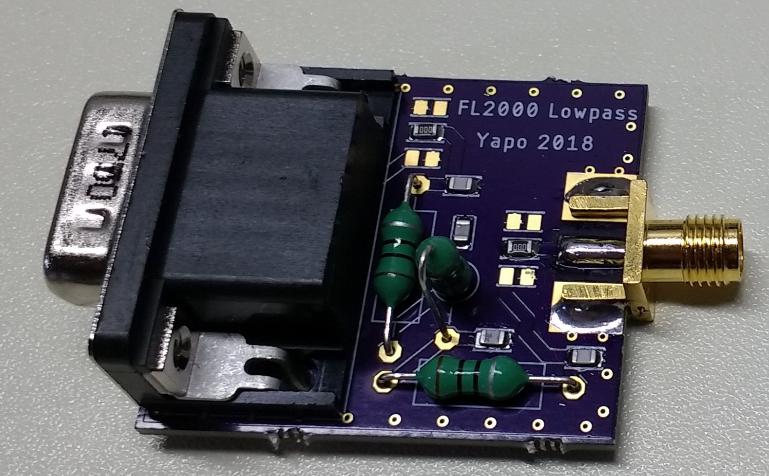
On the PCB, I added pi networks on the front and back of the filter for attenuation or matching purposes, but I just populated the "through" element with a zero-ohm resistor for testing.
This schematic shows 1.5nF caps because I initially couldn't locate decent 1.6nF ones. 1.6nF is the correct value.
I used through-hole inductors because they were the best ones I could find in terms of SRF and Q. The three of them are mutually perpendicular to reduce magnetic coupling, since they are unshielded.
Here are the parts used:
PCBs can be ordered on OSH Park
- (1x) Amphenol VGA Connector, MFG# 10090926-P154XL, DigiKey# 609-4022-ND.
- (3x) Bourns 10uH inductor, MFG# 77F100K-TR-RC, DigiKey# 77F100K-TR-RCCT-ND.
- (2x) Murata 1600pF 0805 Capacitor, MFG# GRM2165C2A162JA01D, DigiKey# 490-12745-1-ND
- (2x) Murata 2700pF 0805 Capacitor, MFG# GRM2165C1H272JA01D, DigiKey# 490-1630-1-ND
- (1x) SMA connector. I got them cheap on ebay. They are 9mm wide.
I also used (2x) 0805 zero-ohm jumpers to bypass the pi networks on the filter. You can substitute a piece of wire or maybe a solder blob.
Here is the output of the voice frequency marker using the LPF:
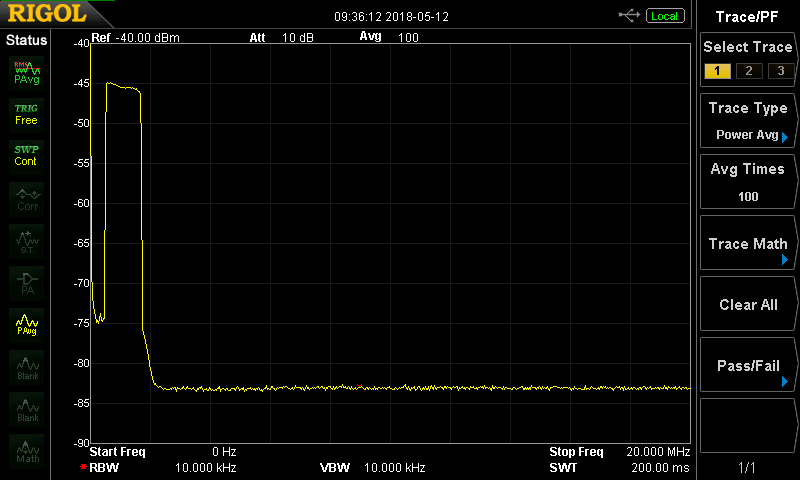
The span extends to 20MHz, and you can see there's really no output above the approximately 1.7 MHz edge of the AM band. Contrast that with the output through the breakout board:
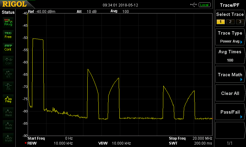
You can see the harmonics mirrored around 8.192 and 16.384 MHz, shaped by a sinc-function due to the zero-order-hold output of the DAC, as explained below. These harmonics are why you need the LPF.
Quick Noise Source
I wanted to test the response of the filter, but I didn't have the right cables and connectors to hook the output from the tracking generator on my spectrum analyzer to the VGA connector. So, I improvised a noise source using the FL2K dongle itself to test the LPF. I grabbed 4 seconds worth of random bytes at 8192k samples/second from /dev/urandom into a file using dd:
dd bs=8192 count=4000 if=/dev/urandom of=noise.dat
these samples can be played through the dongle with fl2k_file:
fl2k_file -s 8192000 noise.dat
The result, shown here played through the breakout, is white noise shaped by a sinc filter:
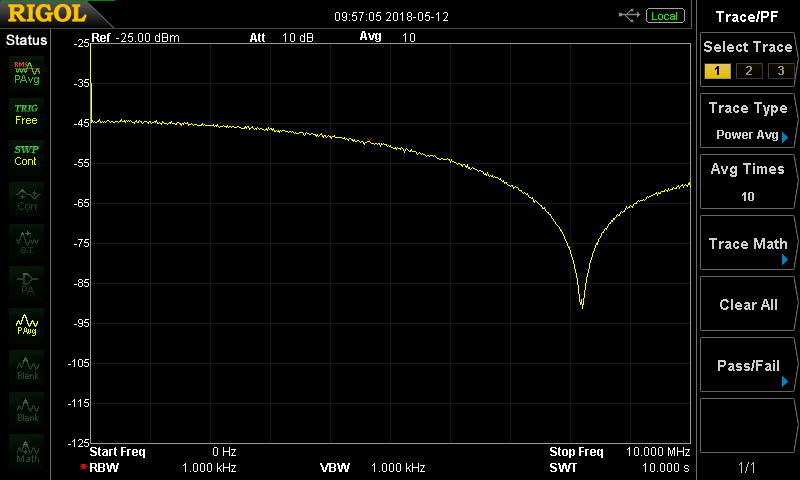
The zero is at the sampling frequency, 8192 kHz in this case. The reason this has a sin(x)/x envelope instead of being flat is the fact that the DAC doesn't have a reconstruction filter: the output consists of a series of discrete steps. In signal-processing parlance, this is known as a zero-order-hold, and you can think of it as a convolution of the input samples with a rectangular pulse as wide as the sample time. Since the Fourier transform of a rectangular pulse is a sinc function, this has the effect of applying a sinc-shaped filter in the frequency domain. For more information, you can check out this Maxim application note. I think I will experiment with some of the techniques in the app note for producing a flatter spectrum - a cheap wideband RF white noise source can be very handy.
Anyway, back to why I did this. Passing the same signal through the lowpass filter reveals an indication of the frequency response:
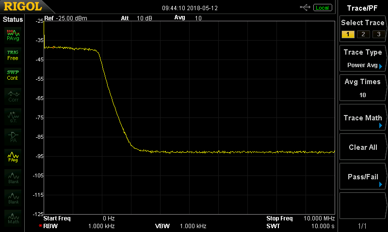
Since the noise input near the passband is close to flat, we can tell that the LPF response of pretty flat out to around 1.8MHz, then drops off at least 50dB. The stopband response shown here is at the noise floor of the analyzer, so it's at least this good, and maybe better.
Re-running the same experiment with a 100 MHz sampling frequency produces the same shape noise with a zero at 100 MHz:
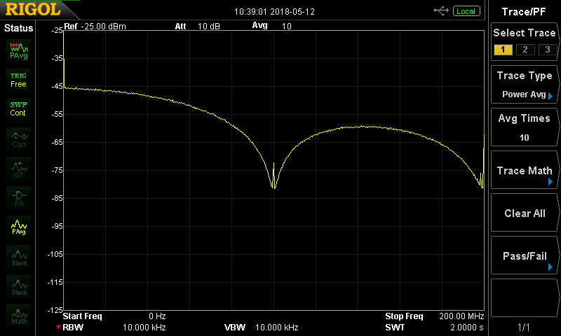
With this signal applied to the LPF, there are no surprises in the stopband:
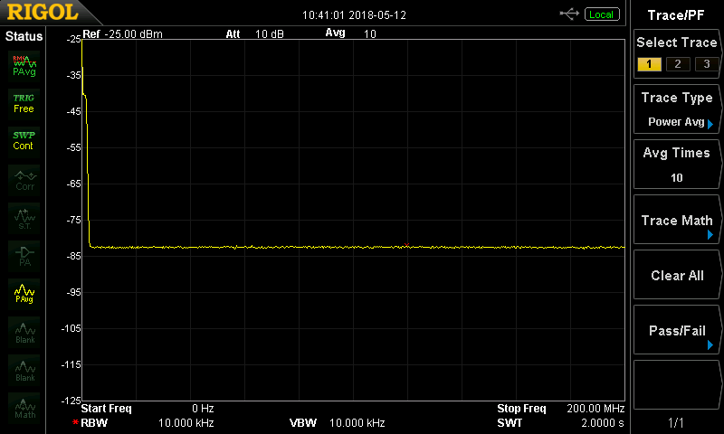
You can just make out the passband at the beginning of the span. Again, the stopband measurement is limited by the analyzer noise floor here.
I'm going to call the LPF a success.
Discussions
Become a Hackaday.io Member
Create an account to leave a comment. Already have an account? Log In.