 Ted Yapo
I threw together a design for a printed coupling coil form in OpenSCAD, then wrapped it with 28Ga wire and attached an SMA pigtail to attach it to the LPF board.
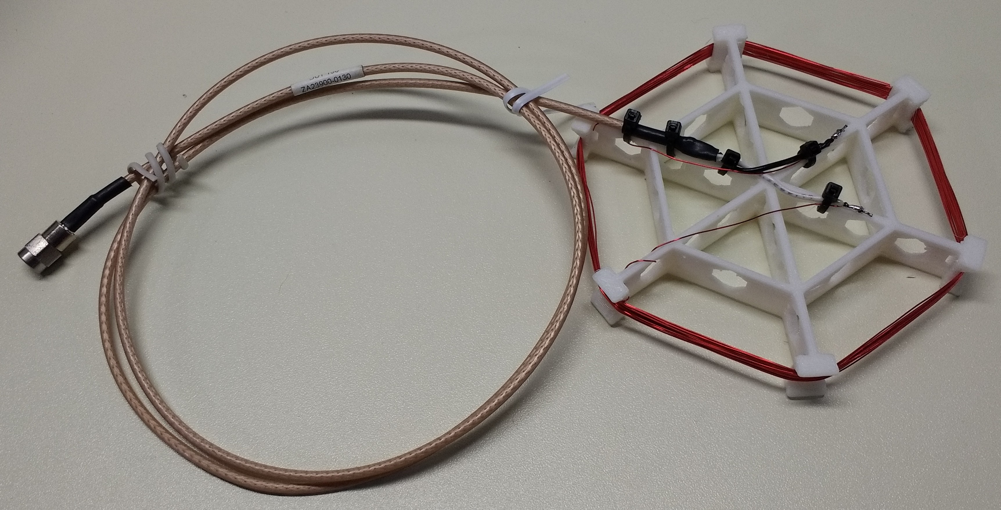
I'm thinking of the coil as the primary side of a transformer, with the "loopstick" antenna inside the receiver as the secondary. The rule of thumb is that transformer windings should have at least four times the system impedance at the lowest frequency of interest. This coil form of around 100mm diameter, wound with 24 turns of 28Ga wire, measures around 165uH. At 500 kHz, this represents a 518 ohm impedance, which is plenty in either a 50 or 75-ohm system.
The form was designed in OpenSCAD, and is in the GitHub repo.
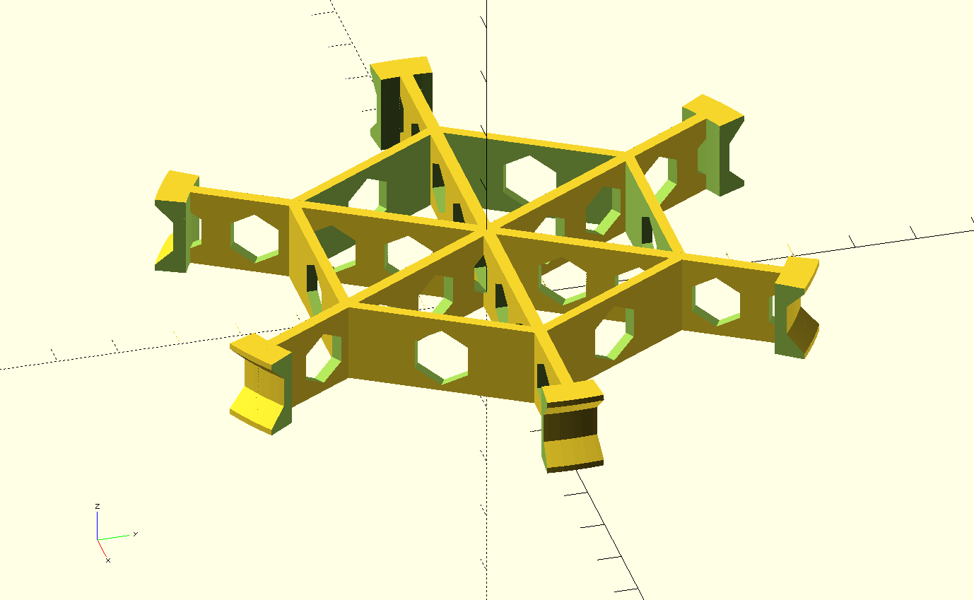
The idea was to save material and keep as much non-air out of the core as possible. I have to imagine that PLA isn't an ideal core material. In any case, it came together quickly, so could probably be improved. After printing, it seems stronger than necessary, so more material could be removed.
How does it work? Compared to the smaller coil (which was only around 17uH), this one gives a stronger signal and alignment with the radio is much less critical. It's sufficient to just have the coil nearby. As an RF alignment tool it's probably as good as it needs to be.
Discussions
Become a Hackaday.io Member
Create an account to leave a comment. Already have an account? Log In.