 Fred Fourie
We're back in the water for a new set of tests (finally)!
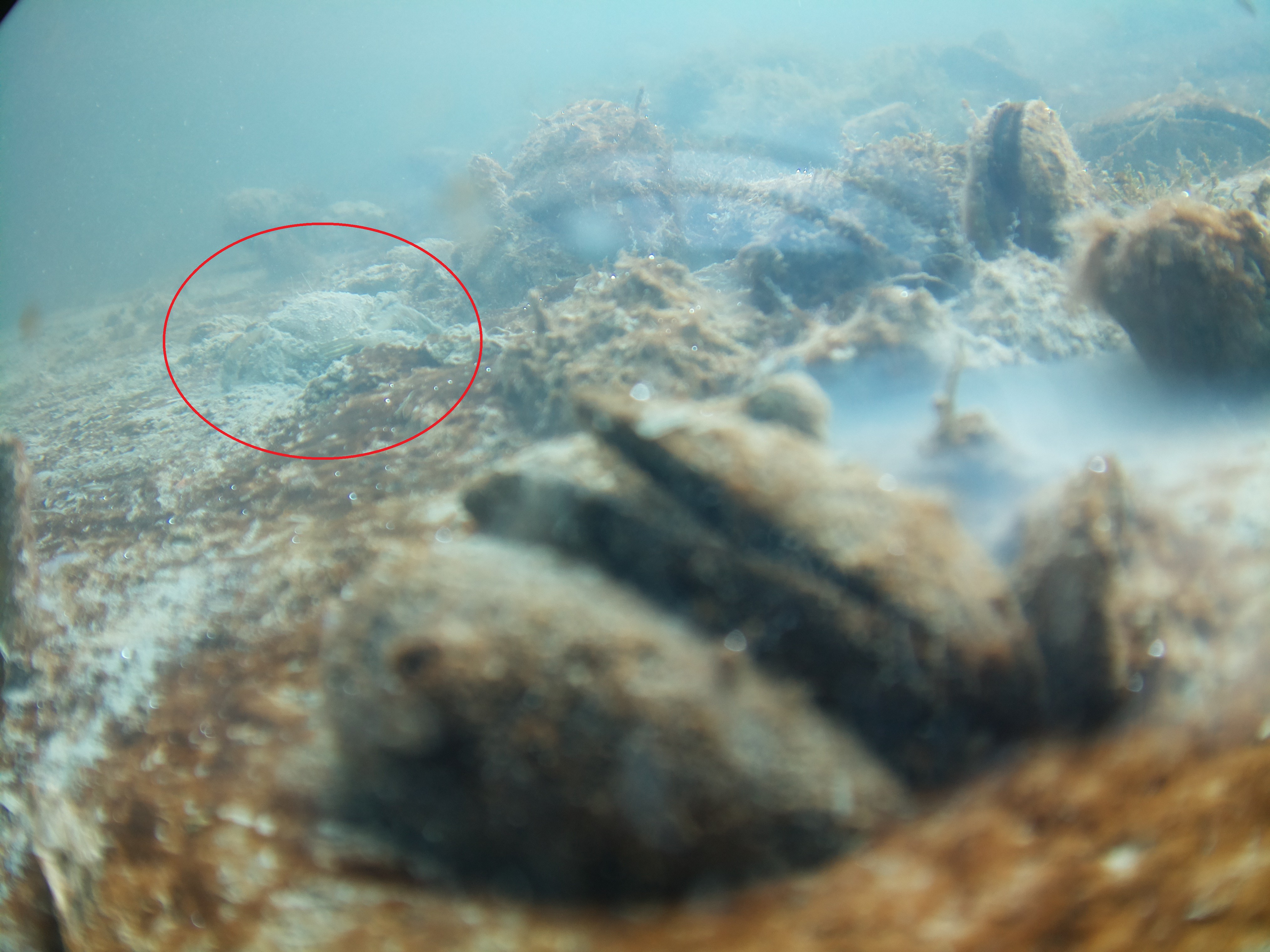
In the image above there are a few things to note, one: the nasty reflection caused by the transparent tube and internal mountings, BUT there is also critter, a small swimming crab passing the camera.
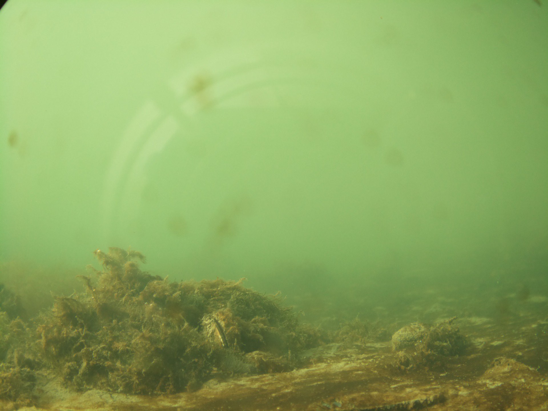
Another shot of a different angle, reflection visible, but a great showcase of the new HQ camera lens set to focus closer.
Here is a quick update on where I am at:
- I'm on the third iteration of a PCB, which was manufactured as V05.03 of the design. Code names Cod (alphabetical fish names for the versions that make it to production).
- PCB design is now two stacking PCBs, one with the MCU and some toys called the "Barnacle board" and the second, a carrier board for the pi, called the "Whale" or "Baleen board".
- PCB is now a larger rounder shape.
- The PVC tube, although bulky, is still the simplest and most reliable housing
- The camera has been upgraded to the Pi HQ camera which has been fantastic
- Current version has not been fully optimised as "low power" yet, but is the lowest power version so far.
- As I write this the camera is in the water for the second test deployment to try and iron out some more kinks. Yes, there are quite a few.
- User interface has been scrapped.
- LCD screen has been scrapped.
- Rotary encoder button has been scrapped.
- Project is still made with primary building blocks off the shelf, but the custom PCBs have some extra peripherals.
There are quite a few design choices to justify, which I will briefly go over here.
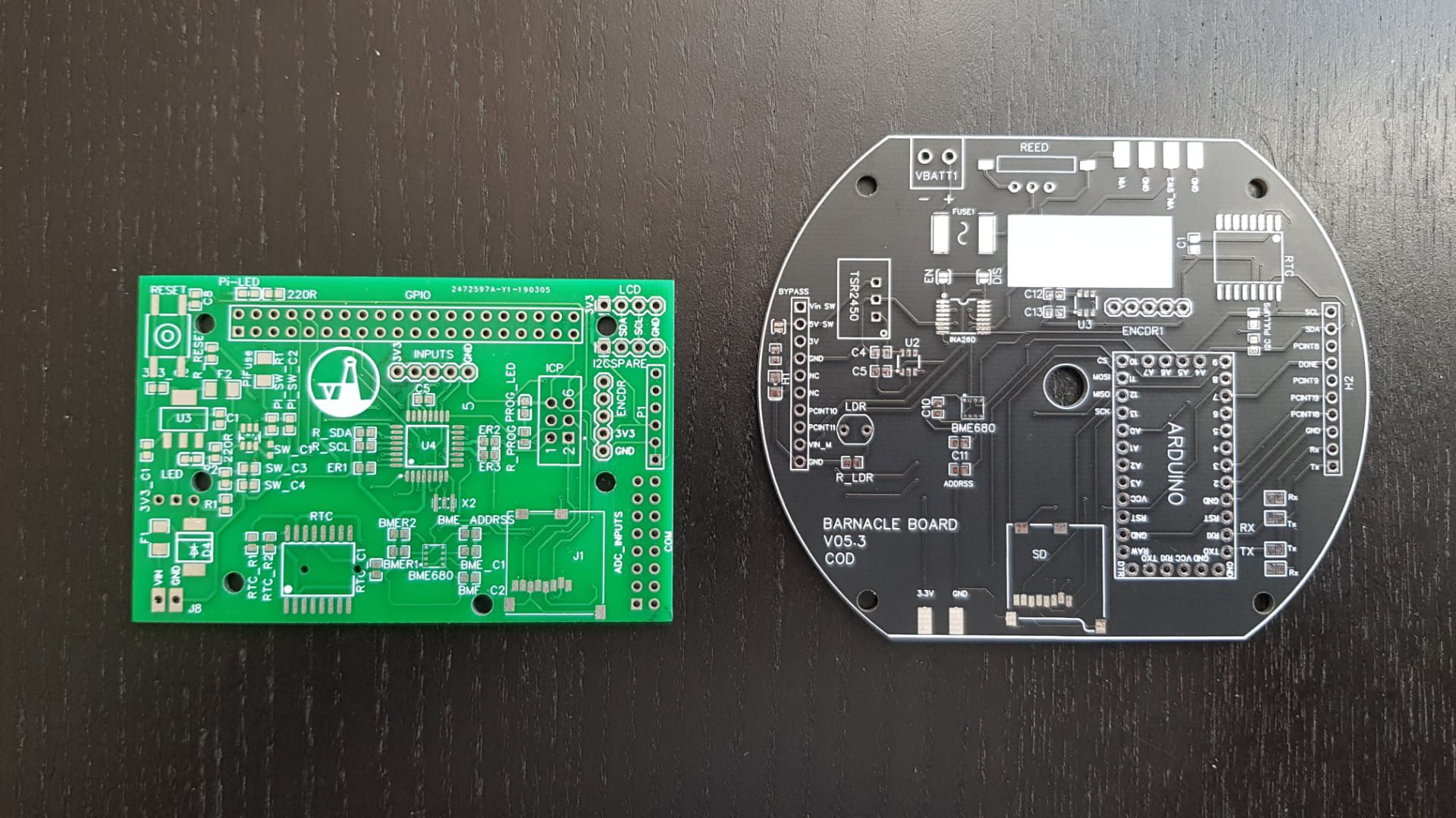
- PCB size. Below is a photo which compares the sizes in the "Ablacore" version (green, left) versus the latest "Cod" version (black, right). The Albacore was ambitious for my skill level at the time. I spent maybe weeks troubleshooting that board and there where many issues I found to be just too time consuming to fix. I found flashing a bootloader not to be trivial. I took a step back and decided that the space I have in the tube would allow for a bigger board, which makes the design easier to troubleshoot and the PCB shape was made to mound easier in the tube.
![]()
- Microcontrollers and the carrier board approach. To it's core, this project is a simple intervalometer. There are tonnes of amazing MCUs to use for something like this. I chose to stick with the ATMega328. Because troubleshooting and flashing over bootloaders was too time consuming at the time, I decided to move away from making a custom MCU board, and just going with a carrier board for an off-shelf arduino clone from Robotdyn. Lastly, frying or bricking an MCU does happen and discarding a pcb that was working perfectly otherwise is a pain for this prototyping phase.
- Stacking boards. The design changes between versions showed me the need to have some versatility in how the boards can be used and instead of planning for every change. The "Barnalcle" stacking on the "Baleen" has proven useful in the design process. Keeping the two parts of the circuit separate has made troubleshooting relatively easy. Plus it looks cool.
![]()
- Scrapping the UI. The Albacore version had a small screen to give users feedback to the mode and settings of the camera. This meant that a LOT of time was going into designing a control method that was intuitive yet still manageable on the firmware side. Although I enjoyed this, I felt that the amount of time it took to get it "just right" kept the project from getting wet.
- Power pack. Initially I decided that the I would go as simple as possible for the power pack for the project. A few iterations in, I decided that this was not good enough. I've used small lead acid batteries and off-the-shelf powerbanks, but found that the 18650 Li-ion battery tech was very mature and super accessible, which pushed me into building some really basic 18650 rechargeable packs. Also- turns out that I really enjoy power pack design. Just not so good at it.

I hope to add some more logs and explanations in the coming weeks as I do more tests.
Discussions
Become a Hackaday.io Member
Create an account to leave a comment. Already have an account? Log In.
Hi Clyde! Thanks for the comment. Yes, I am still using the zero. I will perhaps show the boards in more detail in another post.
I have some comparative tests planned with the HQ and V2.1 cameras. For the HQ camera I am using the 25mm lens (see the link below). I did tweak the V2.1 camera focus, but for the next test I will document how I did this. I don't recall any distortion, but I will look out for it. I found focusing on both these cameras to be a bit of a pain. Also because focusing in air for underwater is deceptive. On land, I aim to have something in focus about 30-50cm from the lens when setting the focus, since I am interested in small, nearer views.
https://www.kiwi-electronics.nl/raspberry-pi/raspberry-pi-camera-en-accessoires/25-mm-10mp-telephone-lens-for-raspberry-pi-camera
Are you sure? yes | no
It's great to see the recent progress! I look forward to the next update.
Are you still using a Pi Zero to connect to the HQ cam? Or a Pi 3? I see what looks like 3 custom boards, but I don't see a Raspberry Pi.
It looks like all of your designs have used a flat plexiglass camera port. Did you have to change the focus on the Pi camera 2.1 to get good results? Do you see any distortion near the edges? For the HQ camera, what lens are you using? Any challenges focusing?
Are you sure? yes | no