-
1Step 1
Remove the four screws on the back of the plug
-
2Step 2
Remove the two smaller screws on the back of the PCB that is attached to the front of the plug
-
3Step 3
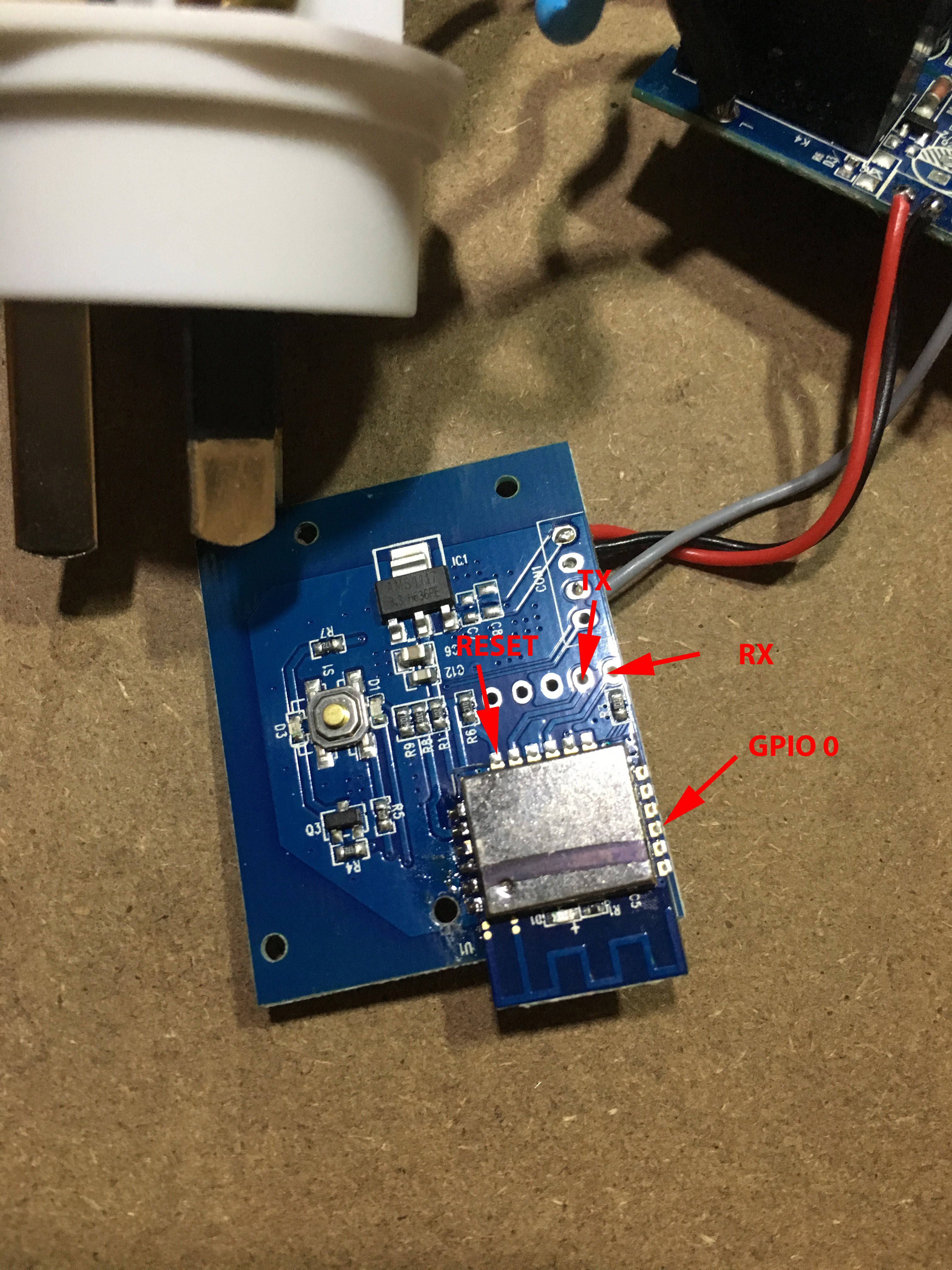
Solder some fly wires to Pins 3 (GPIO 0) and 12 (Reset) of the ESP8266 daughter board. Solder wires to the TX and RX pads on on conn 2.
![]()
Remember that if GPIO 0 is held low on a reboot (ie reset is triggered by pulling the RESET pin low), the device is in programming mode.
-
4Step 4
Connect up each wire to an FTDI plug. You can see the wiring diagram here. DO NOT HAVE THE DEVICE PLUGGED IN TO THE MAINS. Wire up a separate +VCC and GND (It's the red and black wires going to CONN 1)
-
5Step 5
Code up and upload new firmware from the Arduino IDE.
Remember:
- GPIO 4 is the Blue LED
- GPIO 5 is the Relay
- GPIO 13 is the button. You want to bind an interrupt handler to GPIO 13
Here is some example code to get you started.
Create a new Arduino project, insert the code, compile and run, then point your browser at http://esp8266.local/on to switch on and http://eso8266.local/off to switch off.
Hacking a Cheap Wifi Outlet
Others have shown cheap Chinese WiFi Outlets can be hacked. Time to see how hard it is. (Hint: not very)
 Myles Eftos
Discussions
Become a Hackaday.io Member
Create an account to leave a comment. Already have an account? Log In.
Wow! Thank you so much for taking the time to write this up! I have just converted my Lingan SWA1 Plugs over to MQTT so I can control them from Node-Red.
Are you sure? yes | no
could I use a USB TTL Serial Cables to access terminal? it has 3.3v supply as well
Are you sure? yes | no