 Anshul Sanamvenkata
One of the BIGGEST problems with modern commercial drones and DIY hobby drones is that they are extremely easy to break. Anyone who has flown one can admit they have broken many frames and motor arms.
There are countless scenarios many pilots have gone through:
- Crashing into a tree or building
- Battery failure in midair leading to free fall
- Flight controller failure keeping the drone from balancing
- Failsafe mistakes
All of these scenarios lead to a broken frames or arms, and cost hobbyists hundreds of dollars to fix.
Another HUGE problem with commercial drones is the closed source nature of their components and communication protocols making customization IMPOSSIBLE. Similarly, hobbyist drones made from off the shelf parts don't quite offer the same customization either since communication is done with radios instead of a more versatile standard like bluetooth.
What is the solution to these problems?
The UnbreakaBLE drone is! With a complete open source platform and easy reprogrammability, pilots can customize everything from the frame to the flight software onboard. In addition, the modular design allows users to break away the arms for easy transportation, and prevents irreparable damage from falls and crashes. Imagine the drone as an easy Lego creation, any damage can be fixed by simply attaching the parts back together. The modular design can be thought of as being similar to the Apple Macbook's magsafe connector. Just bringing the motor arm close to the frame will automatically pull the arm into place.
In summation, this project will help solve the problems with commercial and hobbyist drones by setting a standard for a more open, customizable, versatile, and durable drone platform.
FEATURES:
- Bluetooth 4.0 with a 6dBm radio offering a range between 15-30 meters.
- Incredibly small PCB with a side of length 15mm.
- Motor outputs are capable of continuous current of 4.2A and peak of 6A, which is more than enough for every mini brushed motor on the market.
- Internal Measurement Unit with 10 degrees of freedom: Accelerometer, Gyroscope, Magnetometer, and Barometer(altimeter).
- 1S Li-Po Battery 500 mAh. Can be switched for a higher capacity battery.
- Smart and safe battery charging over USB with notification LEDs.
- USB 2.0 full speed capability
Ideas and Future Possibilities:
- Possibility for Swarm Robotics given the low cost of the components.
- Inter-Communication between individual drones with Bluetooth Low Energy capabilities
- Apps for various bluetooth devices including smartwatches, tablets, etc.
- Further development of current android app.
- Start development of app for iOS.
Modularity:

As the CAD image above shows, the modularity aspect of this frame comes from neodymium magnets placed in the circular holes at each arm joint. Connection to the board inside is done with spring loaded pogo pins that when connected sit flush into the frame.
Working Prototype:
As a precursor to this current project, about an year ago I built a working prototype. The prototype used an older processor, less accurate sensors, and used only 4 motors(quadcopter). It was a huge success, and was one of the smallest drones in the world at the time. The prototype was merely a test of the PCB and circuitry. It did not have the modular capabilities of the final version.
Now 1 year later, the final version is 1.5 times smaller than the prototype, has battery charging capabilities, includes USB for programming, utilizes more accurate sensors, and has an altitude sensor.
Pictures and video of the prototype:


**NOTICE**: I know there is a lot of contention between using the words "drone" or "multicopter". I am opting to use the less accurate term "drone" since it is how most products are advertised these days and since the word is more recognizable to...
Read more »


 Next, use the HM-11 pinout diagram below to solder wires to the following pads:
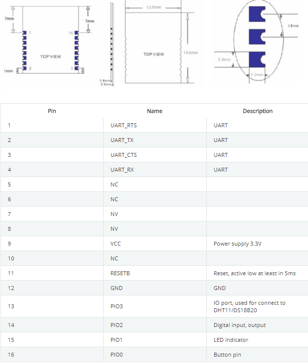
 Peter Wasilewski
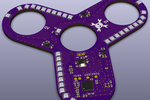
 Matthias
 Michael Frank Taylor
 Eric
Eric