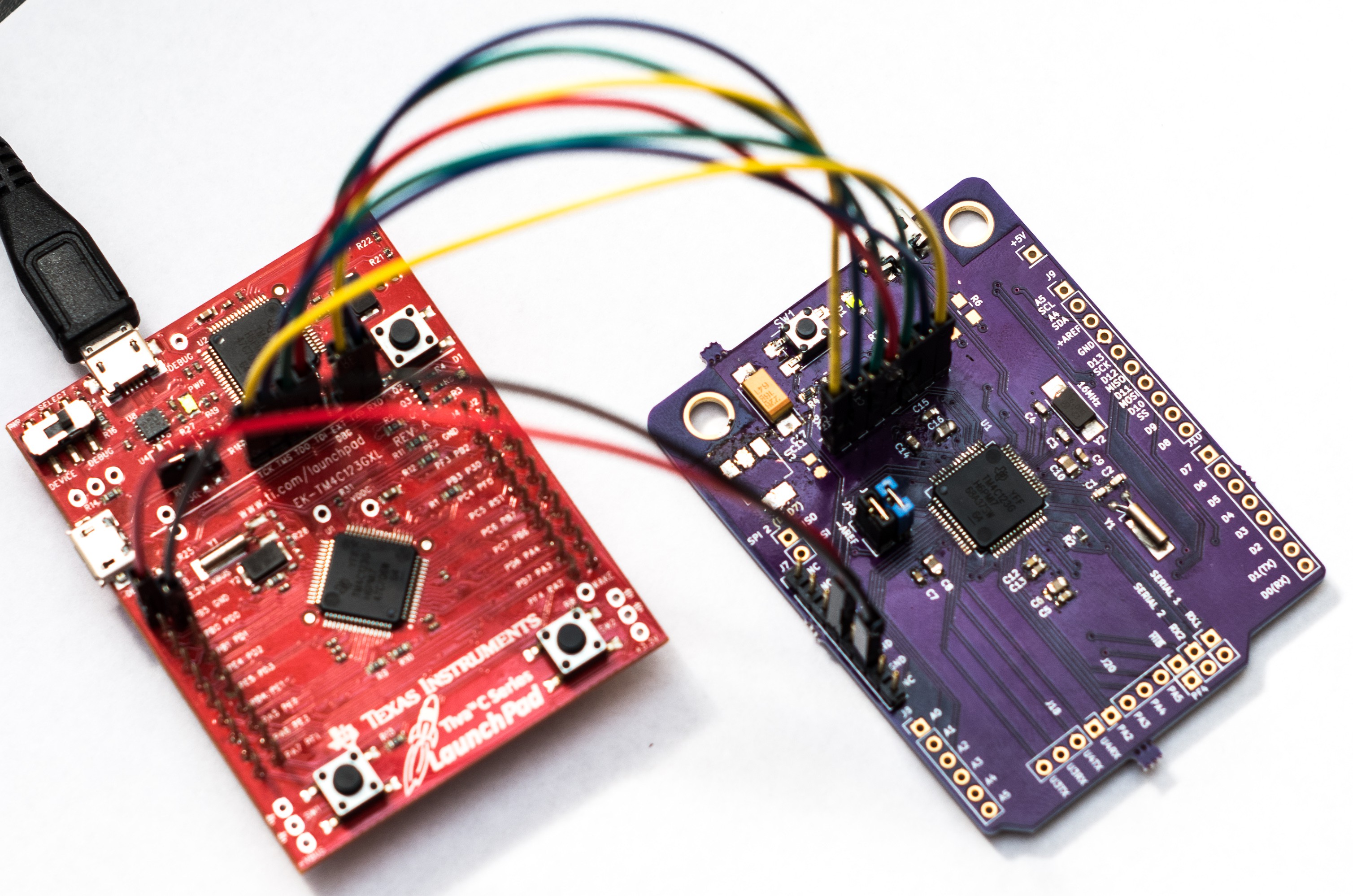
I built another board today using only the minimal number of components required to support running the microprocessor. I then tested it and got the same result from LM Flash programmer as I had before - No communication with the board. Surely I had made a mistake in my schematic. I decided to take time later today and hit the forums to see if someone else could spot the mistake.
I then had a stroke of inspiration. I had left the VDDA and GNDA disconnected on the two boards I tested, thinking they were not important to the initial board bring up. I decided that I should connect them properly and retest. Well... that was the missing element it seems. Taking a look in the datasheet at section 24.6.1 "VDDA Levels", it clearly states
The POR monitor is used to keep the analog circuitry in reset until the VDDA supply has reached the correct range for the analog circuitry to begin operating. The POK monitor is used to keep the digital circuitry in reset until the VDDA power supply is at an acceptable operational level. The digital Power-On Reset (Digital POR) is only released when the Power-On Reset has deasserted and all of the Power-OK monitors for each of the supplies indicate that power levels are in operational ranges.
Lesson Learned: Read your chips documentation thoroughly.
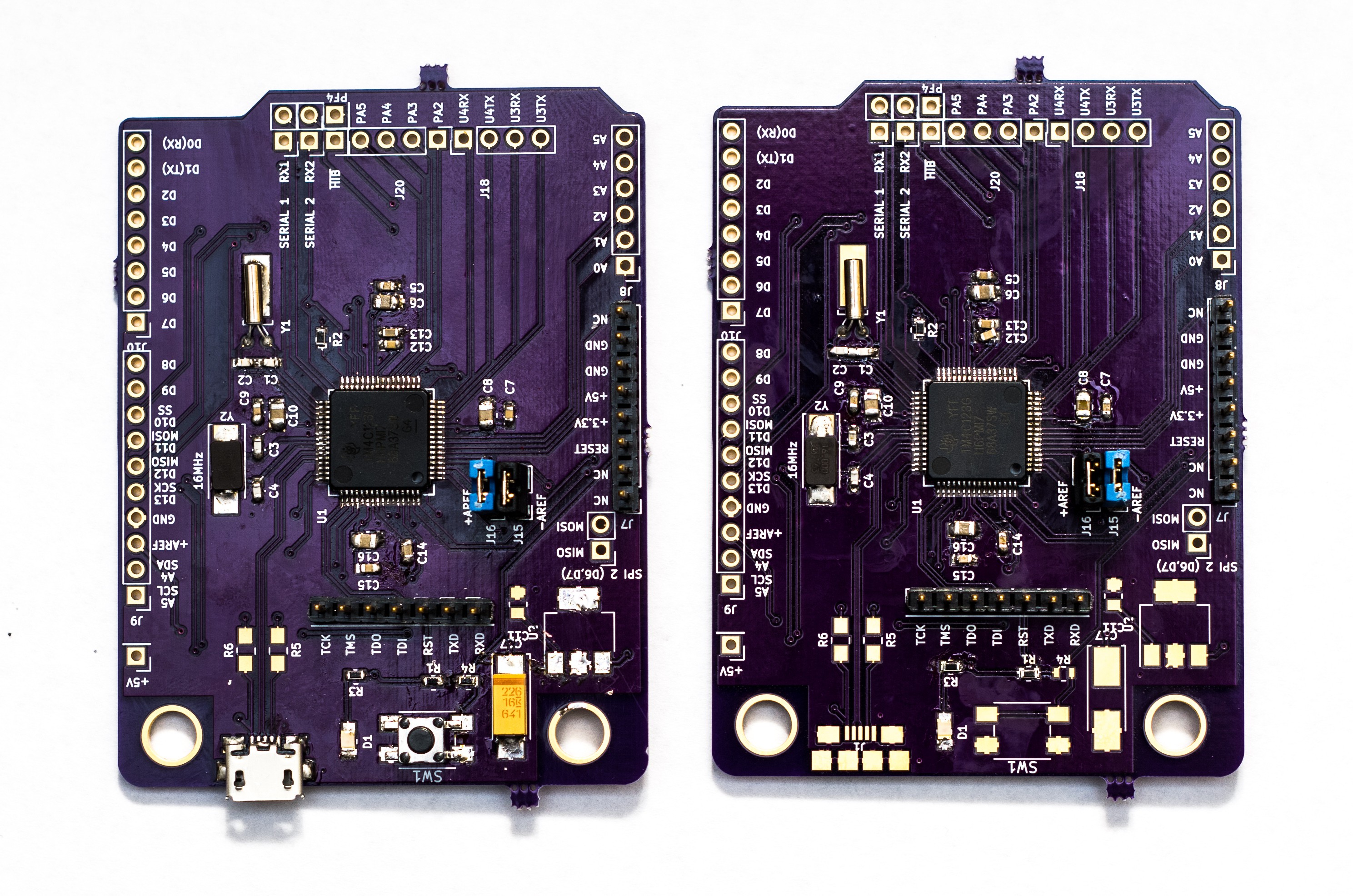
I now have two functioning boards that I can program in Energia and receive serial data over the COMM port monitor. Here are pictures of the the two bards, both in different states of being populated

Discussions
Become a Hackaday.io Member
Create an account to leave a comment. Already have an account? Log In.