 Paul Nicholls
With the init scripts for adb-server and stf now in place, and the stf init script tweaked to wait 10 seconds (for the wifi to connect) and automatically determine the Compute Stick's IP address to pass to `stf local`', nearly everything was set.
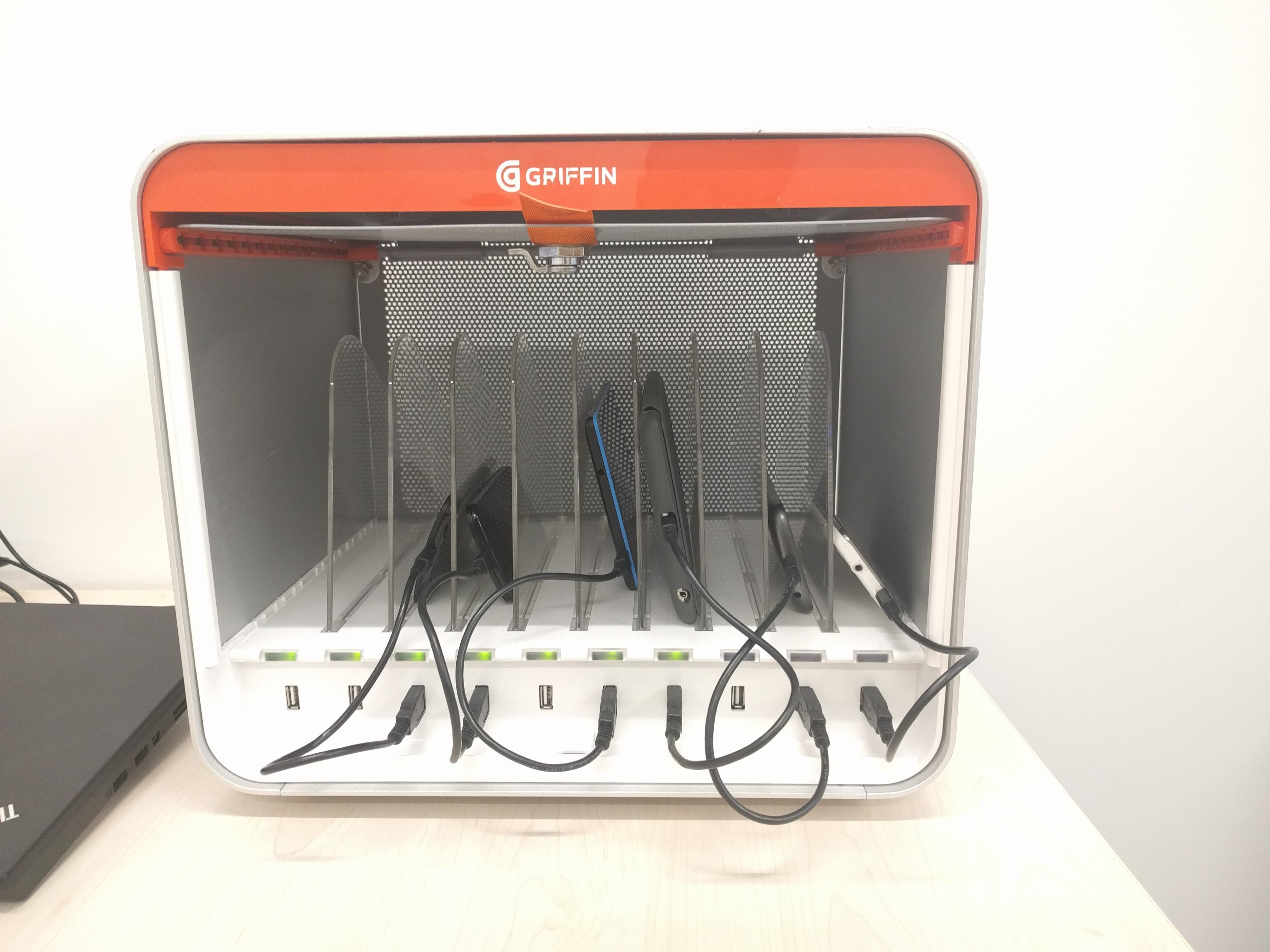
External USB ports for the Orico hub
In order to maintain the external appearance of a stock MultiDock 2, and to remove the need to physically modify the enclosure, I decided to replace a few of the MultiDock's USB ports rather than add additional ports. It'd start to get cramped if you tried to fit more than 10 devices into the MultiDock anyway, so it's not terribly limiting. I found some short USB extension leads with panel-mount ports on AliExpress, and once they arrived, I designed an adaptor plate to take the place of an original MultiDock riser card. It took a few revisions, but once I'd got it dialled in, I printed a few off. With the panel-mount ports I bought (and probably most readily available ones, unless you can find slimline ones), it's necessary to cut a small chunk out plastic off the body of the panel-mount socket; I could have designed an adaptor plate which didn't require this, but it would have been more difficult to print reliably, and would have made it bigger and bulkier. You can find the adaptor plate on Thingiverse.
Preparing the hardware
While removing the main PCB from the MultiDock in order to replace the USB socket with an internal USB cable (to plug into the Orico hub), I noticed that the internal power supply is quite potent - 12V @ 12.5A, or 150W. Since I was removing 3 of the original ports to replace them with ports from the Orico hub, I figured there ought to be plenty of power available - especially since most of the devices won't go anywhere near the 3A @ 5V which it could theoretically supply per port - to skip fitting a separate power supply in for the Orico hub, and instead power it straight off the 12V output of the MultiDock's PSU.
I removed the PCB from the Orico hub, soldered a wire link across the momentary power button so that it powers up automatically, and tacked a couple of chunky wires on to the power pins from the DC barrel jack. I then used some Sugru to mount the Orico hub at one end of the MultiDock, as well as to provide strain relief for the USB cable which is now soldered on to the MultiDock's main board in place of the original socket.
Assembling the STFDock
When the Sugru had been setting for a while, I attempted to assemble everything, only to realise that I'd mounted the Orico hub vertically - which meant that there was no space to plug anything in to it (spacious though the electronics cavity may be, it's not terribly tall). Luckily, I was able to get a spudger under the Sugru and prise the hub free, and remount it (with more Sugru, of course) onto the side of the MultiDock, where it just narrowly fits under the device shelf - but with enough space for devices to be plugged in horizontally. The power leads which I tacked on to the Orico hub simply screw in a pair of the MultiDock PSU's output terminals.
The Compute Stick fits nicely on the opposite side of the MultiDock to the Orico hub; as I may want to remove it at some point, I decided against Sugru, instead using some blu-tack. It doesn't have a lot of wiggle room anyway, though there are some exposed metal surfaces/objects which the HDMI plug could potentially bump into should the Compute Stick come loose - so I covered the exposed metal (and the HDMI plug) with masking tape before mounting the Compute Stick. Two USB cables run across the interior of the MultiDock - the micro USB cable which came with the Compute Stick to power it from the Orico hub, and the USB3 cable which came with the Orico hub, to plug the hub into the Compute Stick. The MutliDock is the plugged in to the Orico hub using the short USB cable which replaces the original external (upstream) USB port.
With the Orico hub and Compute Stick installed, I then reinstalled 7 of the 10 original riser cards (one port was blocked by the Compute Stick's USB cables, so I had to reroute all 7 cables to the next port along from their original locations), along with the three 3D printed adaptor cards with panel-mount USB extension leads fitted (which plug directly into the Orico hub). It's a bit of a tight squeeze, as the USB cables between the Orico hub and Compute Stick are quite a bit longer than necessary, but all fits in without any great difficulty.
Testing and finishing off
Before putting the MultiDock back together, I thought it best to test everything one last time. I plugged a power cord in, flicked the switch, waited for STF to start up and then plugged a phone into each port in turn, waiting for it to appear in the STF web UI and initialise. Once I'd confirmed that all ports were working as expected, I powered it down and finished reassembling the case. I then plugged it back in and powered it up, and was relieved to find that it all still works - the STFDock is now complete!
Although the STFDock is now complete, there is still room for improvement. The first enhancement which comes to mind is the indicator LEDs - the three ports connected to the Orico hub don't have externally visible indicator LEDs at all, so they almost appear "dead". The Orico hub does have and individua LED for each port, which lights when a device is plugged in to it - so if desired, it would be feasible to either pipe the light from the existing (blue) LEDs to the relevant locations in the MultiDock case (perhaps using fibre optic strands) or remove the LEDs and remount them (or replace them with another colour - perhaps even rigging up a bi-colour setup similar to the original MultiDock ports) on long enough cords to attach them in place of the original LEDs.
Discussions
Become a Hackaday.io Member
Create an account to leave a comment. Already have an account? Log In.