Close
0%
0%

Linear Position Sensor for Actuators OpSo

Trying to make an easy to use but low cost linear position sensor without optical sensors. OpSo = Open Source

Similar projects worth following
370 views
Why?

Because I need this. I created a new actuator system that's modular, but I need a feature to be able to read where the position of the actuator is.

Here's some constraints I want to work within:

- Non-optical sensing because of dirt or unreliability in some situations
- Should hopefully be low power consumption for battery applications.
- Sensors or wiring shouldn’t move with action. Since the rod of the actuator is what I need to track, I don’t want any wires hooked up to it.
- Able to live outside of the actuator body preferred so can be serviced or installed without removing the inside rod.
- Instantly be able to detect where the position is on power up.
- Doesn’t need to be high speed, about 1khz would be good enough.
- Keep it somewhat cheap. $2-$3 per inch or so would be great.
- Able to be trimmed anywhere between sensors to size without major mods to keep full functionality.
- 4 pin target for output (including 2 power), but

As a starting point, I'm making a simple external "visual" array of sensors to see where the actuator would be on the inside.

The basic idea:

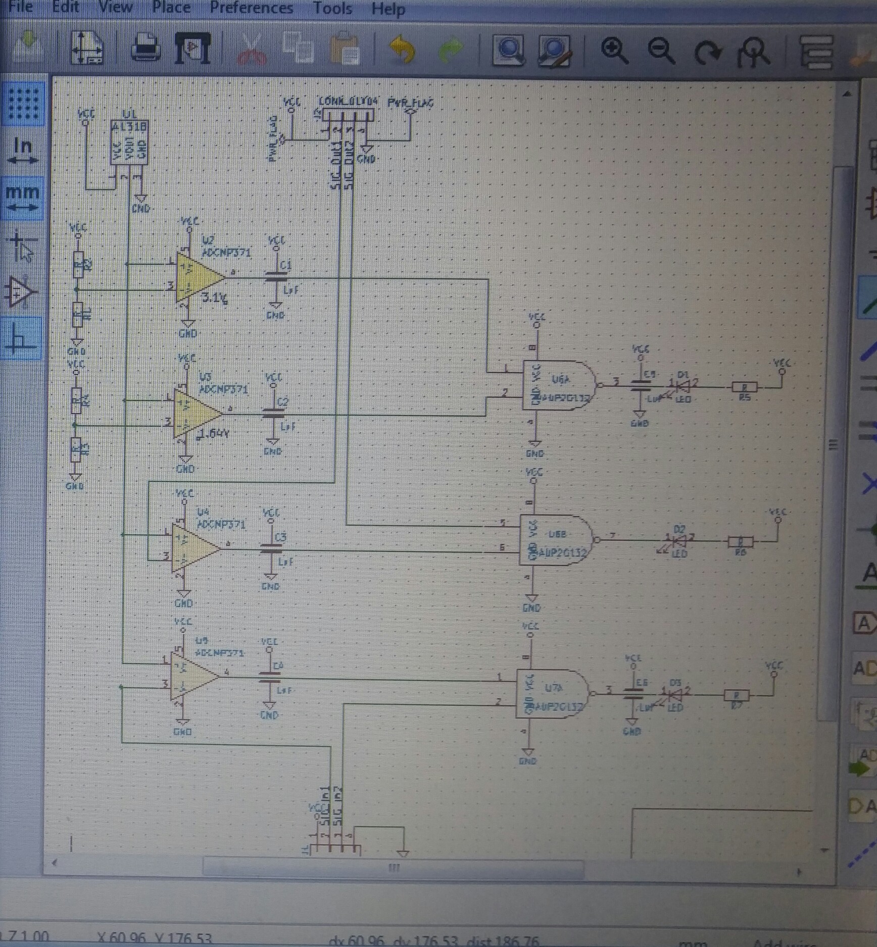
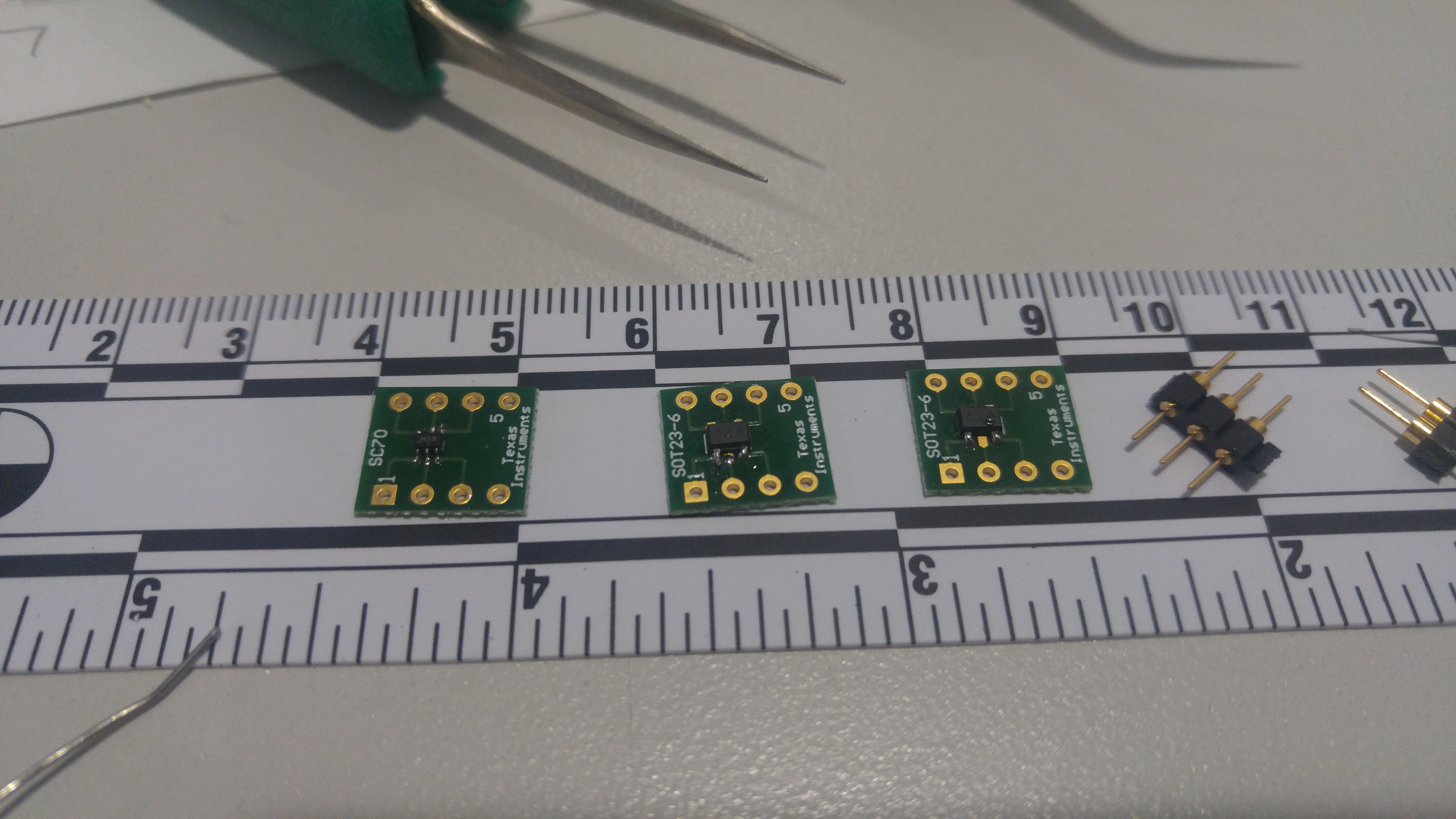
Bottom of board has Hall effect sensors spaced evenly (spacing to be determined after some testing).

Each Sensor would have 2 or 3 LEDS under it to indicate the magnet's rough position. This is done by getting a voltage level of the adjacent sensor to see which side it's coming from.

  • 1 × Allegro A1318 Linear voltage hall effect sensor

  • Space constraints and board routing

    Deviza05/18/2017 at 18:56 0 comments

    I finally had time to get the circuit into Kicad and found all the appropriate chip footprints. The linear distance requirements of the sensor are dictating the board dimmensions. I'm running into issues with via spacing and routiing, even with the small components. It looks like I will need to test the slightly stronger model of the sensor instead Hopefully I gain a few mm of board space. Here is a picture of the madness.

    Yeah I know, picture of a monitor and all...

  • Breadboard prototype seems to be functioning

    Deviza05/11/2017 at 00:20 0 comments

    I forgot to mention that the hall effect sensor under test is the Allegro A1318.

    Link to buy the part: https://www.digikey.com/short/3nf1m2

    So I first finished the pre-logic stage of the circuit and tested the output values. This was done so that I know exactly what the logic will see. Leds were used to visualize this, also I don't have six volt-meters but an 8-channel logic probe would have worked also.

    Video featuring pre-logic stage


    The next step involved testing with some AND logic chips. In the final version we will be using NAND chips because of the ability to sink more current than source. But since the NAND chips are a very small footprint VSSOP-8 and I don't currently have a breakout board for them, I used AND in DIP footprint. One change, not depicted in the following video, was to move the sensors closer and eliminate dead-space in the transition.

    Video featuring full prototype on breadboard:

    Now it's time to get all this back into EagleCad and hopefully etch a full working prototype strip. Maybe in time for Maker Faire, hopefully. Not really sure how these very small traces are going to fight me quite yet.

    Stay tuned: More to follow!

  • Components for testing

    Deviza05/08/2017 at 18:24 0 comments

    I have recently received the order of components to breadboard the first prototype.

    Initial testing has shown something interesting and unexpected. The linear voltage hall effect sensor when powered on has a baseline output of ~1.64v. If i place a North facing magnet on a surface and move it towards the sensor, the voltage output initially decreases. I decided to measure and graph the outputs. Based on the results, with the test magnet, at about 10mm the voltage breaks the 1.64v threshold. I will basically have to slightly re-think my approach and set any value above this threshold to be a valid input to the board logic. More to come soon...

    Note: When dealing with SMT, always buy extra... Because somehow they end up jumping onto the floor and vanish.

    Video featuring Allegro A1318 Hall effect sensor voltage threshold testing:


  • Schematics in progress...

    Deezmaker04/21/2017 at 02:11 0 comments

    Currently working the schematics and then going to wire up a quick prototype to see if it even works.

View all 4 project logs

Enjoy this project?

Share

Discussions

Similar Projects

Does this project spark your interest?

Become a member to follow this project and never miss any updates