Close
0%
0%

Eagle parts, by family, using python

A quick collection of python scripts to make a whole family of parametric parts in eagle.

Similar projects worth following
145 views
0 followers
This project was born after some students of mine needed some surface mount headers. i had an old eagle library i had made by hand. the students found no end of problems with it. first the pins were mixed up. a bit of grunt work later, that was solved, they ordered boards and low and behold: the parts were to big for the pads. and that was the last straw.


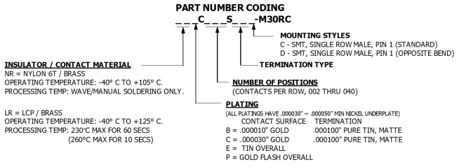
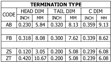
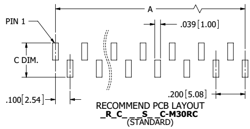
This project doesn't really need many logs, the entire process took only a few hours from start to finish. But the process may be of use to others. the problem stems from the figure above. it lists the dimension C without a number associated. you can find that measurement in a table based on what family/type of component you purchase, hence all the blank spots in the part number ending with M30RC.

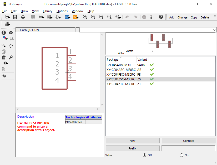
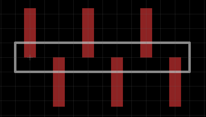
To complicate this situation, these headers come in sizes from two pins to 40, and four or five varieties plus each variety has a mirror image, That sounds like 300-400 different footprints. So how do i script eagle? ULPs are not a good fit for me for 2 reasons:

  1. They don't allow you to move or place items very well.
  2. I don;t remember how to code in that pseudo c language.

So a quick look at SCR files shows that there are no looping or math functions available, it seems that ULPs usually return a SCR script to modify things in the sch/brd/lib file; but as per reason 2 above, i don't want to learn ULPs. so python will be used instead.

the rest of the project is making custom EAGLE commands with the correct arguments.


plain - 1.16 kB - 04/22/2017 at 02:17

Download

ConnectSullins.py

link all the created footprints to a device

plain - 719.00 bytes - 04/22/2017 at 02:17

Download

plain - 1000.00 bytes - 04/22/2017 at 02:17

Download

  • part 3 of n

    bveina04/22/2017 at 04:25 0 comments

    The humble header device in eagle.


    If you've made your own components in EAGLE you already know the process, if you havent (you should), there are 3 basic steps

    1. make footprint (for pcb)
    2. make symbol (for schematic)
    3. connect them pin to pin to make a device

    multiple footprints can be connected to a single symbol. and this is handy for many reasons. By the end of the last log i had made 5 variants for each of 20 different pin counts. That's a lot of pin to pin connections. Naturally Im going to want to script this as well.

    the overall approach is the same as making footprints, but the EAGLE commands get a little more involved.

    basic psudo code first:

    for each pinCount from 2 to 20:
      delete old device
      create new device
      add schematic symbol
      for each footprint
        create a device 'variant'
        connect the pins 1-to-1
    

    first off how to delete and create devices?

    REMOVE deviceName;
    ADD deviceName;

    well that settles that. i settled on a very generic HeaderNN where NN is the number of pins, zero padded.


    I thought that adding the schematic symbol would be harder than it turned out to be. turns out to be relatively straightforward. as long as your not too picky about your origin point.

    ADD deviceName (0 0);

    all of this requires a bit of careful object naming.

    Devices: HEADERnn

    Symbols: Hn

    Packages: see previous post insanity...

    so the code to create all the package variants is:

    nameTemplates = {"SABN":"G*C{0:02d}SABN-M30",
                     "AB":"XX*C0{0:02d}ABC-M30RC",
                     "FB":"XX*C0{0:02d}FBC-M30RC",
                     "ZS":"XX*C0{0:02d}ZSC-M30RC",
                     "ZT":"XX*C0{0:02d}ZTC-M30RC"}
    cmd1="""remove header{0:02d}.dev;
            edit header{0:02d}.dev;
            add H{0:d} (0 0);"""
    cmd2="package {0} {1};"
    myCMDs=[]
    for p in range(2,20+1):
      myCMDs.append(cmd1.format(p))
      for typeKey,typeVal in nameTemplates.items():
        myCMDs.append(cmd2.format(typeVal.format(p),typeKey))
    

    This adds in the package command. every package must have a "variant" name. this helps differentiate parts. I created a dictionary with my "variant" as the key and the package name for that variant as the value. This tells EAGLE to have all 5 variants available for use with one schematic symbol. They still need to be connected pin to pin.

    Connection is simplified by the naming scheme on both the devices and the footprints. i use the numbers 1-20, period.

    the EAGLE command "CONNECT" lets you connect multiple pins with a single command, due to my clever naming scheme, to connect a 4 pin variant the command is

    CONNECT 1 1 2 2 3 3 4 4 

    in python i can build the command for any number of pins as:

    connectCMD="connect "
        for x in range(1,p+1):
          connectCMD+="{0} {0} ".format(x)

    this is not optimal string handling in python, but

    At this point i can see the finish line, lets get this done!

    nameTemplates = {"SABN":"G*C{0:02d}SABN-M30","AB":"XX*C0{0:02d}ABC-M30RC","FB":"XX*C0{0:02d}FBC-M30RC","ZS":"XX*C0{0:02d}ZSC-M30RC","ZT":"XX*C0{0:02d}ZTC-M30RC"}
    
    cmd1="remove header{0:02d}.dev;edit header{0:02d}.dev;add H{0:d} (0 0);"
    cmd2="package {0} {1};"
    
    myCMDs=[]
    for p in range(2,20+1):
      myCMDs.append(cmd1.format(p))
      for typeKey,typeVal in nameTemplates.items():
        myCMDs.append(cmd2.format(typeVal.format(p),typeKey))
        connectCMD="connect "
        for x in range(1,p+1):
          connectCMD+="{0} {0} ".format(x)
        myCMDs.append(connectCMD)
    
        myCMDs.append("write")
          
    with open("test.scr","wt") as f:  
      for x in myCMDs:
        f.write(x+"\n")

    and with that i now have all my variants nicely setup:

    This wraps up this build log. I've posted the scripts in the files section and i hope this inspires someone to make other scripts to deal with product families that are parametrically similar.

    I may tackle double row headers in a later post.

  • Part 2 of n

    bveina04/22/2017 at 03:40 0 comments

    Last time, I successfully made a python script that made a single component, but that made several assumptions, first, i was already in the footprint editor with a named component. if i was going to make ~200 components i would need to open many new footprints and name them in an intelligent way.


    NAMING

    From the Datasheet

    All of these blank spots above can be filled in to form valid part numbers. only some of these cause changes to the footprints.

    • the number of positions
    • the termination type

    So, part numbers can be represented as "***CnnnSttC-MR30RC" where

    • * is dont care
    • n is number of pins
    • tt is termination type

    That is enough to make unique package names.

    nameTemplate = "XX*C0{0:02d}{1:s}C-M30RC"
    terminationTypes={'AB':.359,'FB':.339,'ZS':.239,'ZT':.239}
    for Key,Val in terminationTypes.items():
      for p in range(2,20+1):
        myCMDs.append("remove '"+nameTemplate.format(p,Key)+".pac'")
        myCMDs.append("EDIT '"+nameTemplate.format(p,Key)+".pac'")

    The EAGLE "EDIT" command will create or open a package,symbol, or device from an open library. you can provide the suffix .pac, .dev, or .sym to explicitly create new items in the library. The remove command is only needed if you are running this script multiple times to debug it. you cant add duplicate pads to an existing footprint, so we just delete it first.

    I've also created a quick dictionary with the measurements for each termination type. it may seem redundant to include both "ZS" and "ZT" variants, they have the same measurements as far as the footprints are concerned. however, i use EagleUp 3d visualization heavily, so its worth it to specify the two variants for later 3d modeling, and since I'm scripting everything, it doesn't really cost me anything either.

    The nested loops above will create footprints for all four variants, each for two to twenty pins.

    Here is everything combined, first in pseudo code:

    for each variant, v
      for each pin count p
        create footprint(v,p)
        for 1 to p
          place SMD pad
        draw documentation

    And the full python:

    hpitch = 0.1
    nameTemplate = "XX*C0{0:02d}{1:s}C-M30RC"
    cmdTemplate = "SMD {0:f} {1:f} '{2:s}' ({3:f} {4:f});"
    cmd1Template = "WIRE .008 ({0:f} {1:f}) ({2:f} {3:f}) ({0:f} {1:f}) ;"
    myCMDs=[]
    terminationTypes={'AB':.359,'FB':.339,'ZS':.239,'ZT':.239}
    for Key,Val in terminationTypes.items():
      outer=Val
      padW=.039
      padH=outer/2
      yPrime = +(padH/2)
      yAlt   = -(padH/2)
      for p in range(2,20+1):
        myCMDs.append("remove '"+nameTemplate.format(p,Key)+".pac'")
        myCMDs.append("EDIT '"+nameTemplate.format(p,Key)+".pac'")
        myCMDs.append("GRID 0.05 inch;")
        x=0
        for i in range(1,p+1):
          if i%2==1:
            y=yPrime
          else:
            y=yAlt
          myCMDs.append(cmdTemplate.format(padW,padH,str(i),x,y))
          x+=hpitch
        myCMDs.append("LAYER tDocu;")
        myCMDs.append("Set Wire_Bend 0;")
        myCMDs.append(cmd1Template.format(-.05,0.05,(p)*.1-0.05,-0.05))
        myCMDs.append("Set Wire_Bend 4;")
        myCMDs.append(cmd1Template.format(-.05,0.05,(p)*.1-0.05,-0.05))
        myCMDs.append("write")
    

    Up to this point I was writing the python in notepad++, copying everything, using the %paste macro in ipython, then printing all the lines, copying them out of the command prompt, pasting them into a temporary file, then running that file in eagle. that got old exactly this fast.

    So a quick addendum to the previous python:

    with open("test.scr","wt") as f:  
      for x in myCMDs:
        f.write(x+"\r\n")

    After some quick cleanup and checking, I am now the proud owner of 200 clean footprints....

    how do i connect 200 footprints to their respective devices?

    more later.

  • Part 1 of n

    bveina04/22/2017 at 03:02 0 comments

    The goal of the project is to make a lot of similar components as quickly as possible using python. the first step was to understand how to do a single component using only the command bar.

    I'll write this log in the order I discovered commands, not the final order they are used.


    1. PAD/SMD

    the core command needed to create a component will be familiar to anyone who has made their own component in eagle. the PAD command places a through hole connection and the SMD command places a surface mount connection.

    the help documentation is pretty good and lists the following information for the SMD command

    SMD [x_width y_width] [-roundness] [orientation] [flags] ['name'] •..
    

    boom

    And now i can place a pa-wait what is that DOT at the end?? well the documentation tells me that is a mouse click. that isn't very useful for scripting. however, that dot can also be replaced with "(xCoord yCoord)".

    now the pad code begins to take shape:

    myCMDs=[]
    cmdTemplate = "SMD {0:f} {1:f} '{2:s}' ({3:f} {4:f});"
    
    for i in range(1,p+1):
          myCMDs.append(cmdTemplate.format(padW,padH,str(i),x,y))

    This will create pads named '1', '2',...,'n', x and y locations. Calculating X and Y are relatively straightforward. X will increase by the pin pitch (0.1"), and Y will alternate.

      hpitch = 0.1
      yPrime = +(padH/2)
      yAlt   = -(padH/2)
      x=0
      p=6
      for i in range(1,p+1):
        if i%2==1:
          y=yPrime
        else:
          y=yAlt
        myCMDs.append(cmdTemplate.format(padW,padH,str(i),x,y))
        x+=hpitch

    The last step in the footprint was to add a quick silkscreen for the plastic part of the header.

    cmd1Template = "WIRE .008 ({0:f} {1:f}) ({2:f} {3:f}) ({0:f} {1:f}) ;"
    myCMDs.append("LAYER tDocu;")
    myCMDs.append("Set Wire_Bend 0;")
    myCMDs.append(cmd1Template.format(-.05,0.05,(p)*.1-0.05,-0.05))
    myCMDs.append("Set Wire_Bend 4;")
    myCMDs.append(cmd1Template.format(-.05,0.05,(p)*.1-0.05,-0.05))
    myCMDs.append("write")


    This code required a few more Eagle commands:

    • LAYER selects what later any wires will be drawn on.
    • WIRE_BEND 0 goes Horizontal before Vertical
    • WIRE_BEND 4 goes Vertical before Horizontal
    • WIRE draws...wires, on the current Layer and supports multi-part lines.

    Boom:

    One down, 199 to go.

View all 3 project logs

Enjoy this project?

Share

Discussions

Similar Projects

Does this project spark your interest?

Become a member to follow this project and never miss any updates