Close
0%
0%

Tiny Tim

Goal: Spend less than $100 on a remote control robot and make it in less than 24 hours.

Similar projects worth following
While there are kits around for simple remote control differential drive robots, I thought it would be cool to make something from some actobotics parts and sparkfun bits that were laying around. To spice it up I decided to get it from random bits to working in less than 24 contigiuous hours... well, 15 because of sleep and stuff :)

https://www.youtube.com/watch?v=rO8b-jkOOaY&feature=youtu.be

Note that the Fritzing file is on the Tiny Tim github repo if you want to play around with it.

On the project page I'll list parts and prices from major USA suppliers. You might choose to use similar bits from China retailers instead.

The two github repos linked to can up uploaded using the Arduino IDE. They rely on the SPI and TWI Arduino library as well as the RF24.h, MultiLCD.h (for the OLED), and Adafruit_NeoPixel if you want the 2812 LEDs to light the way. I will probably make the code GPLv3, see respective source files for final say.

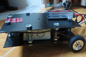
Screws from the battery mount, Tamiya wheel and beam mounting all come through the channel. The 170 tie breadboards can then be slighly sanded and inserted into the channel for the electronics.

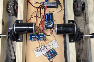
For the gearmotors and their enclosures, I superglued the motor into its case. Otherwise it tended to slide a little bit which wasn't ideal.

More details to follow here...

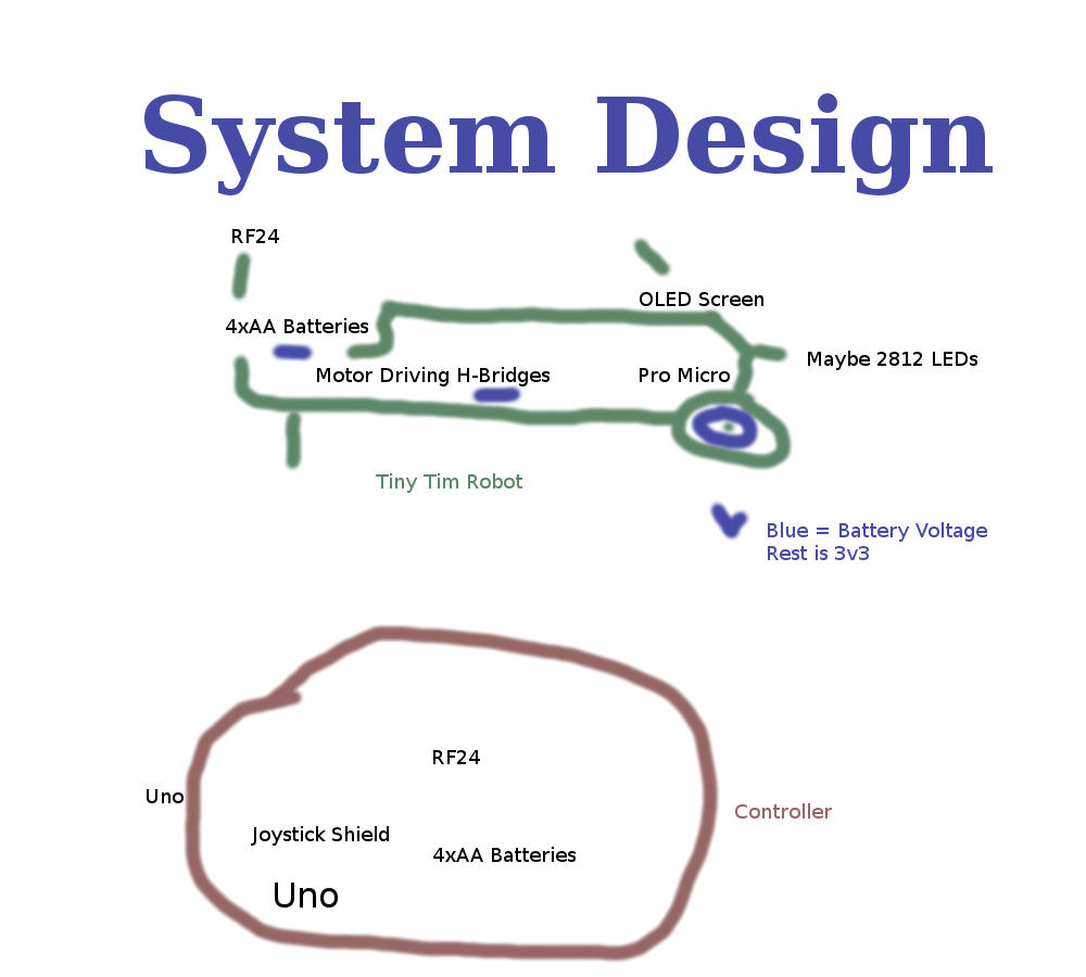
Remote control is simply the joystick shield ontop of the Uno. I hard wired the radio to the top of the joystick shield because it didn't have pass throughs and I wanted the rustic look.

  • 2 × 4 inch Actobotics Heavy Duty Wheel
  • 2 × Micro Gearmotor Enclosure
  • 2 × 30 RPM 6 volt micro gearmotor
  • 2 × Actobotics Aluminum Beam - 3.85" (11 holes in beam) These reach out from the core body to hold the gearmotors
  • 1 × Actobotics Aluminum Channel - 4.50" This is the core "body" of the root

View all 26 components

  • Crude system design added

    monkeyiq08/07/2014 at 04:10 0 comments

    Sort of working from end to start, but here is a system design that I had in mind while throwing it together.

  • Adding a manipulator Claw

    monkeyiq08/07/2014 at 03:27 0 comments

    Next up will be adding in a small metal gripper so Tim can move things around... https://www.sparkfun.com/products/11524

  • Two screens, two eyeballs

    monkeyiq08/02/2014 at 22:35 0 comments

    The OLED screen can be one of two TWI addresses, depending on if one pin is low or high. So I might move to having two screens side by side as "eyeball" displays. Adding the mouth is a little harder unless I desolder things on one screen to turn it into an SPI interface.

  • Two 2812 LEDs, one on each side

    monkeyiq07/31/2014 at 11:22 0 comments

    Attached to the Side Mount Brackets that hold the screen channel on. Having the LED aimed downward at the floor and along the main channel makes it easier on the eyes, those 2812 are extremely bright.

    Currently I'm running them colour syned to the wheel power. Low/no power = red color, high power = red+(g|b) depending on the side.

  • Attaching the motor enclusures to the beams

    monkeyiq07/31/2014 at 11:20 0 comments

    Normal nuts come loose fairly quickly, nylocks seem to be holding ok for that.

View all 5 project logs

Enjoy this project?

Share

Discussions

Similar Projects

Does this project spark your interest?

Become a member to follow this project and never miss any updates