Ok, here we’re going to go through the 6502 ALU (and my implementation of it), since it’s relatively straightforward and independent of the rest of the CPU. Below I’ve included the block diagram of the ALU.
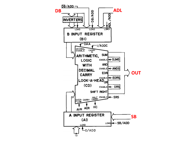
It’s got two 8-bit input registers (A and B), both of which can be filled from several different inputs. The B input can additionally be fed with an inverted data bus, allowing the ALU to do subtraction. There are 5 intrinsic operations: add, and, or, exclusive-or, and shift right. The add instruction can also do subtraction, when combined with the inverted data bus. There is a carry-in and carry-out, to allow for >8-bit operations. There is also an overflow bit that detects signed over- or underflow. On the block diagram there are a few other input and output bits, but those are used only for the 6502 decimal mode which the NES CPU does not implement, so we’ll ignore them.
I won’t talk about the input or output registers here, as I decided to have the ALU module be independent of them. I included them in the diagram in order to highlight the inverted DB input. In my ALU, I moved the inversion into the ALU itself rather than outside the B input (because it was cleaner? I dunno, it just happened). So the inputs to the ALU module consist of the A and B registers, the carry bit, and the control signals (the operations plus the inversion signal). One final change is that I included an extra operation, rotate right. That was done purely for convenience, since I’m still not quite sure how this was implemented on the actual 6502 (can anybody clarify?).
With that, here’s the code:
module ALU(
    input wire SUM_en, AND_en, EOR_en, OR_en, SR_en, INV_en, ROR_en, // Operation control
    input wire [7:0] Ain, Bin, 					     // Data inputs
    input wire Cin, 						     // Carry in
    output reg [7:0] RES,					     // Operation result
    output reg Cout, 						     // Carry out
    output wire OVFout						     // Overflow out
    );

    // Declare signals:
    wire [7:0] Bint;

    // Select inverted or non-inverted B input:
    assign Bint = INV_en ? ~Bin : Bin;

    // Perform requested operation:
    always @(*) begin

	// Defaults:
	RES = 0;
	Cout = 0;

	// Operations:
        if (SUM_en)
	    {Cout, RES} = Ain + Bint + Cin;	// add with carry-in, carry-out
        else if (AND_en)
            RES = Ain & Bin;			// and
        else if (EOR_en)
            RES = Ain ^ Bin;			// xor
        else if (OR_en)
            RES = Ain | Bin;	                // or
        else if (SR_en)
            {RES, Cout} = {Ain,1'd0} >> 1;	// shift right with carry-out
	else if (ROR_en)
	    {RES, Cout} = {Cin,Ain,1'd0} >> 1;	// shift right with carry-in, carry-out

    end

    // Set overflow flag (set if both inputs are same sign, but output is a different sign):
    assign OVFout = (Ain[7] && Bint[7] && (!RES[7])) || ((!Ain[7]) && (!Bint[7]) && RES[7]);

endmodule
As noted above, the B input inversion in handled inside the ALU module, for reasons. Each operation is handled in a separate case. The input carry bit is used for add and rotate right operations. Carry output is changed for add, shift, and rotate operations (auto cleared for logical ops, but the rest of the CPU will ignore it in those instances). The overflow bit is an interesting one (the best reference for understanding it is Ken Shirriff’s blog: http://www.righto.com/2012/12/the-6502-overflow-flag-explained.html), it basically detects when an operation results in a number that can’t fit in a signed byte (for example: 127 + 1 = -128, instead of +128). To calculate it, the ALU checks that if both inputs (after inverting B if necessary) are the same sign, the result should also be that sign. If it’s not (again, +127 + 1 = -128), then the overflow bit is set. By inverting B, the same math works for subtraction and negative inputs.
One note here is that the ALU relies on the programmer to correctly set the carry input for the requested operation. For example, for a normal 8-bit add, the carry bit should be cleared before the operation (for >8-bit adds, the carry is cleared for the first op, and then the carry out is used for the next byte(s)). For subtraction, the opposite is true – the carry bit should be set prior to an 8-bit subtract. That’s because, for subtraction, the carry bit acts as a “borrow” bit. You can also think of it like implementing an add of the 2’s complement of the input (so to subtract B from A, you invert B and set the carry, so that the result is adding –B to A). Again, for >8-bit subtracts, the carry out is used for the next byte(s).
And… that’s about it! The implementation of the ALU is pretty simple, the real magic comes in the different ways you can manipulate the inputs and controls in order to do some cool things.
Discussions
Become a Hackaday.io Member
Create an account to leave a comment. Already have an account? Log In.