Now we’ll get into a concrete instruction example: ADC. This instruction will add a number to the accumulator register, and will then store the result back in the accumulator and set some flags based on the result. And we’ll start with one of the simplest addressing modes: immediate addressing. In this mode, the byte that you want to add is actually stored right next to the opcode in the program code (and was, in fact, hardcoded into the program as a constant), so that you just have to increment the program counter and fetch the byte. Since we have multiple addressing modes for this one instruction, we’ll denote this one “ADC_IMM” (for obvious reasons).
Ok, so the operations that take place on each cycle are:
Cycle 0: Fetch the ADC_IMM opcode
Cycle 1: Fetch the byte to add
Cycle 2: Add the byte to the accumulator, and fetch the next opcode
Pretty simple, I suppose. Note that, since we’re fetching the next opcode at the same time that we perform the add, this instruction technically only takes 2 cycles (you can count cycle 3 as cycle 0 of the next instruction), which is the basis for the 6502’s pipelining. Now, we’ll look at how to translate those basic steps into actual CPU operations:
case (cycle)
  0: begin
    case (IR)
	ADC_IMM: begin  // next cycle: store ALU result, fetch next byte
	  I_cycle <= 1;							// increment cycle counter

	  PCL_ADL <= 1; ADL_ABL <= 1; PCH_ADH <= 1; ADH_ABH <= 1;	// output PC on address bus
	  I_PCint <= 1; PCL_PCL <= 1; PCH_PCH <= 1;			// increment PC

	  ADD_SB <= 1; SB_AC <= 1; SB_DB <= 1;				// move ADD to AC through SB
	  AVR_V <= 1; ACR_C <= 1; DBZ_Z <= 1;	DB7_N <= 1;		// add result flags to status reg
	end
    endcase
  end
  1: begin
    case (IR)
        ADC_IMM: begin  // next cycle: ALU add, fetch next opcode
	  R_cycle <= 1;							// reset cycle counter to 0

	  PCL_ADL <= 1; ADL_ABL <= 1; PCH_ADH <= 1; ADH_ABH <= 1;	// output PC on address bus
	  I_PCint <= 1; PCL_PCL <= 1; PCH_PCH <= 1;			// increment PC

	  DL_DB <= 1; DB_ADD <= 1; AC_SB <= 1; SB_ADD <= 1; SUMS <= 1;	// perform ALU add on AC, DL
	end
    endcase
  end
endcase
It may help if we start in Cycle 1, and if we ignore the last line. Actually, let's reformat a little bit:
case (cycle)
0: begin
case (IR)
ADC_IMM: begin // next cycle: store ALU result, fetch next byte
I_cycle <= 1; // increment cycle counter
PCL_ADL <= 1; ADL_ABL <= 1; PCH_ADH <= 1; ADH_ABH <= 1; // output PC on address bus
I_PCint <= 1; PCL_PCL <= 1; PCH_PCH <= 1; // increment PC
ADD_SB <= 1; SB_AC <= 1; SB_DB <= 1; // move ADD to AC through SB
AVR_V <= 1; ACR_C <= 1; DBZ_Z <= 1; DB7_N <= 1; // add result flags to status reg
end
PREV_OP: begin // next cycle: fetch next byte
I_cycle <= 1; // increment cycle counter
PCL_ADL <= 1; ADL_ABL <= 1; PCH_ADH <= 1; ADH_ABH <= 1; // output PC on address bus
I_PCint <= 1; PCL_PCL <= 1; PCH_PCH <= 1; // increment PC
end
endcase
end
1: begin
case (IR)
ADC_IMM: begin // next cycle: ALU add, fetch next opcode
R_cycle <= 1; // reset cycle counter to 0
PCL_ADL <= 1; ADL_ABL <= 1; PCH_ADH <= 1; ADH_ABH <= 1; // output PC on address bus
I_PCint <= 1; PCL_PCL <= 1; PCH_PCH <= 1; // increment PC
DL_DB <= 1; DB_ADD <= 1; AC_SB <= 1; SB_ADD <= 1; SUMS <= 1; // perform ALU add on AC, DL
end
PREV_OP: begin // next cycle: fetch next opcode
R_cycle <= 1; // reset cycle counter to 0
PCL_ADL <= 1; ADL_ABL <= 1; PCH_ADH <= 1; ADH_ABH <= 1; // output PC on address bus
I_PCint <= 1; PCL_PCL <= 1; PCH_PCH <= 1; // increment PC
end
endcase
end
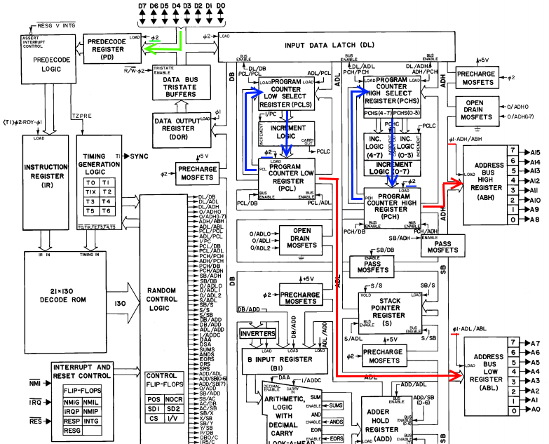
endcaseOk, now we'll start in Cycle 1, and we're currently executing the previous operation (so IR equals the cleverly named "PREV_OP" opcode). Here, the next cycle will be the last cycle of this instruction, so we need to go out and fetch the next opcode (which will be the ADC_IMM instruction). We're going to reset the cycle counter to zero (the R_cycle command). To fetch the next opcode, we're going to put the current program counter (PC) out on the address bus and increment it at the same time to point at the next byte in the program. As shown below (in red), on the next phase 1, the PC will be latched into the external address bus registers. On phase 2 of that cycle, the returned data from that address (the opcode) will be latched into the predecode register (in green), and the incremented PC latched into PC (in blue)
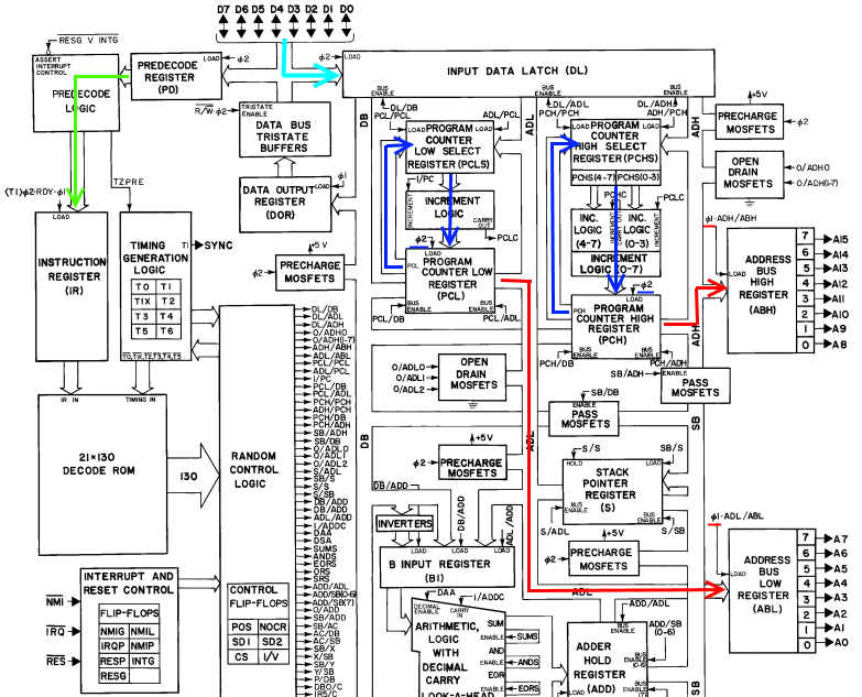
So, now we're in phase 2 of Cycle 0. PC has been incremented, the ADC_IMM opcode is in the PD register. However, IR is still equal to PREV_OP, since the next opcode hasn't reached it yet. So according to the case statement, we're in Cycle 0 of PREV_OP. We know that we've just fetched the next opcode, though, so we're going to go ahead and fetch the next byte (whatever it is, since we don't know which opcode we fetched yet). This 2nd fetch happens on every cycle 0, since we won't know about the opcode for another cycle. Ok, so to do that, we're just repeating the same commands, except we're incrementing the cycle instead of restarting it. The block diagram is the same as above, except on the next phase 1 we'll load the new opcode into IR, and on phase 2 we'll load the fetched byte into the input data latch DL.
 Ok, now we're in phase 2 of cycle 1. The PC has been incremented again, and now IR contains the new opcode, ADC_IMM. So in the case statement, we finally get to do some instruction specific stuff! We're going to send the fetched byte (the operand that we'll add to the accumulator) from the DL register to the B input of the ALU (the DL_DB and DB_ADD commands). We're also going to send the accumulator to the A input of the ALU (the AC_SB and SB_ADD commands). And finally, we'll tell the ALU to add the 2 inputs together (SUMS). We've also reached the end of this instruction, and thus need to fetch the next opcode, so we'll increment the PC, send it out to the address bus, and reset the cycle count. So on phase 1, the address for the next opcode will be sent out, and on phase 2, the PC is incremented, the next opcode is latched into PD, and the add result is latched into the ADD register:
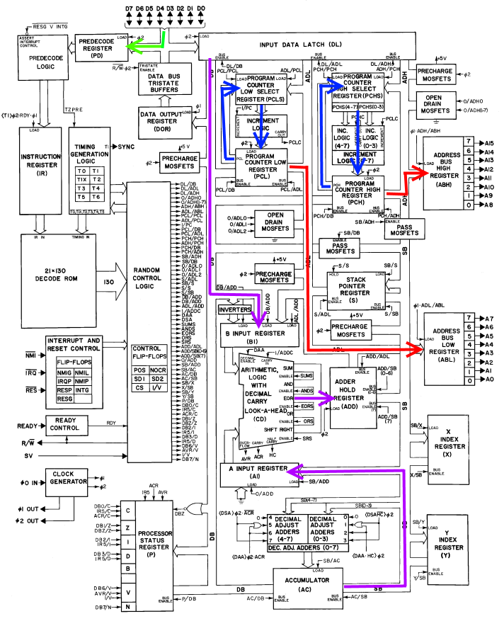
Ok, so we're in cycle 0, we've executed the add and fetched the next instruction. But IR is still equal to ADC_IMM, and we have two more things to do for this instruction. First, we need to store the result back into the accumulator.
Second, after most instructions, the CPU will set various flags based on the result of that instruction. This will tell the programmer various things, so you can test, for example, whether two numbers are the same, or one is greater/lesser than another. These flags are held in the processor status register (P, in the block diagram). Since we just completed the addition, the ALU is still outputting several flags about the resulting number (namely, the carry flag - was the unsigned result >255?, and the overflow flag - was the signed result >127 or <-128?), and two more flags will also be stored in the status register (the zero flag - was the result == 0?, and the sign flag - was the result positive or negative?). However, we still need to get the flags to the P register.
We'll do both of these things by sending the ADD register to the SB bus (ADD_SB). The accumulator will latch that value directly on the next phase 1 (SB_AC). The SB value will also be sent to the DB bus (SB_DB). Then, the zero flag will be latched into P on phase 1 by doing a NOR on the DB bus (DBZ_Z), and the sign flag will be latched from bit 7 of the DB bus (DB7_N). The other two flags will be latched directly from the ALU (ACR_C and AVR_V).
And finally, in addition to all that, we'll also fetch the next byte while we're loading the fetched opcode into IR.

And now we're in Cycle 1 of the next opcode (whatever it is), we've fetched the next byte of that instruction (whatever it is), we've updated the accumulator to its new value, and we've set the flags based on that value. Whew!
Discussions
Become a Hackaday.io Member
Create an account to leave a comment. Already have an account? Log In.