 Luc Vachon
The project started out as a 555 timer based flyback driver. I wanted easier control of the frequency and duty cycle, so I decided an Arduino was needed. Normal Arduino PWM frequencies are far too slow for a flyback, so I used a library that modifies the clock scaler to bring the PWM frequency into the 20-30Khz range needed. This reduces resolution at higher frequencies, but I that's a trade-off I was willing to take.
I wanted to give this thing a semi-intimidating look, and I feel red 7-segment displays are the most ominous, so I used a pair of 70XX demuxes (one an inverted version of the other) to drive a 4pack of them.
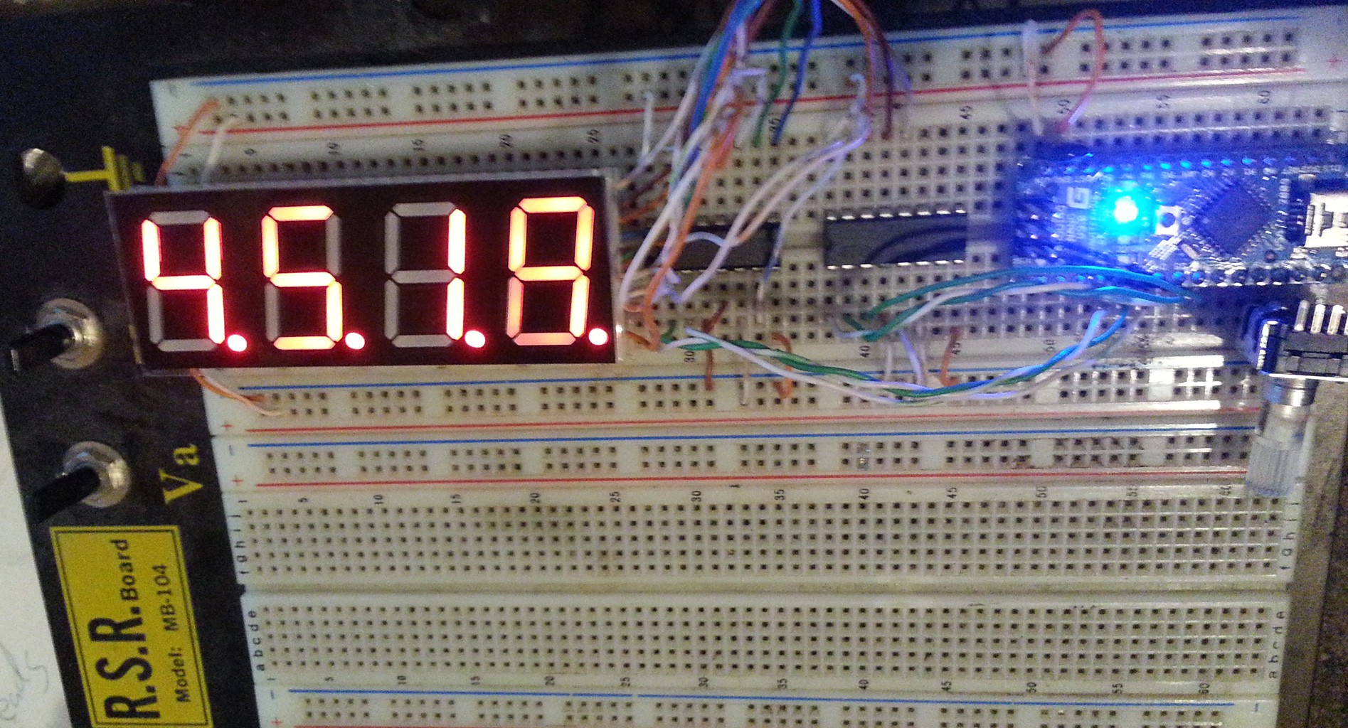
Finally, I wanted the interface to be simple. So a rotary encoder switch was used, giving me rotation information and a momentary switch in one package.
I thing the processor is quite busy keeping up with the PWM clock, polling the rotational encoder, and driving the display, nothing but demuxing is offloaded to other hardware.
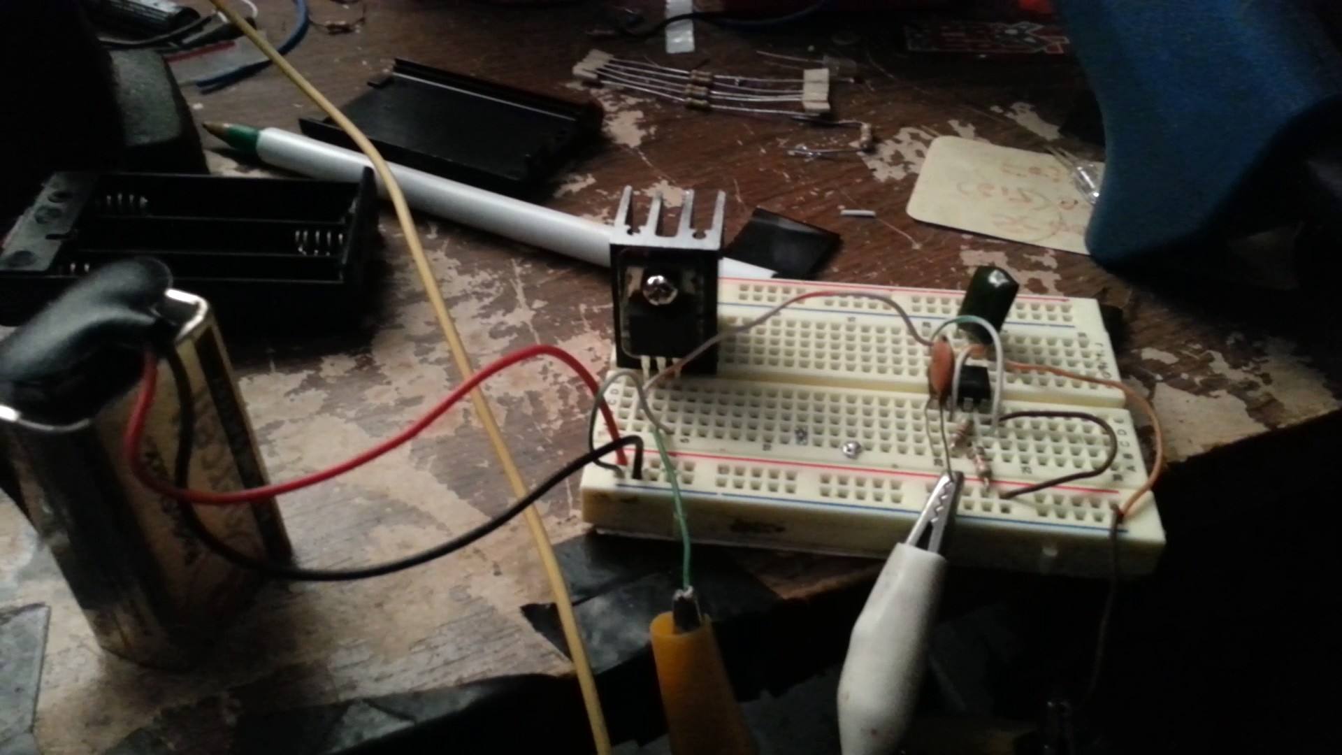
The big switching transistor is a big-ol MOSFET, with a bipolar transistor driving the gate. Anything from 6-20ish volts will work, but I fear I'll need a much bigger heatsink if I try any more than 12V.
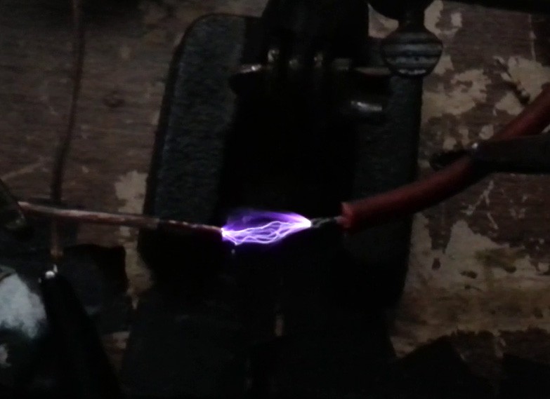
My intention is to close the feedback loop by having the Arduino monitor and regulate the high voltage coming from the flyback. However I'm nervious about creating a direct conduction path from the HV output to the MCU, I don't have any proper HV resistors, and this flyback is making 1" arcs. I imagine trying to bodge a divider out of normal resistors is just asking for an arc to ruin my day.
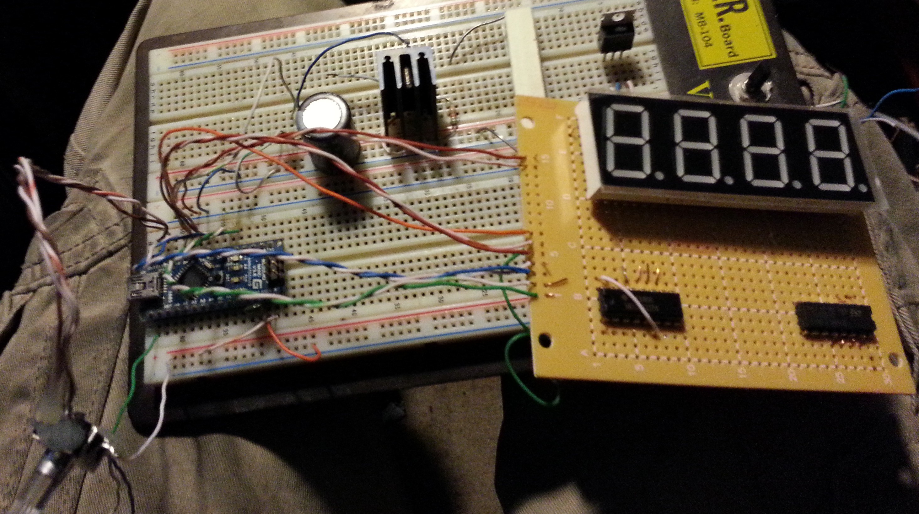
Currently, I'm soldering up my breadboard prototype. The 7-Seg and demuxes are done (the hard part), next is the MCU socket and analog components. In the end they'll be encased in a nice cast aluminum case.

 biemster
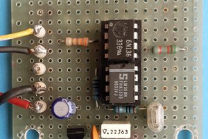
 Giovanni Carrera
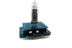
 My Electronics
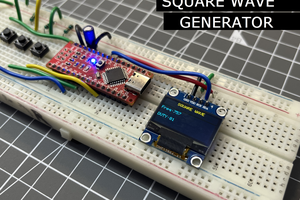
 Sagar 001