 Casual Cyborg
This is my very first development board project. After shrinking about 15k worth of equipment to a custom board the size of a credit card that can read your muscle signals, to winning TechCrunch Disrupt's 2015 Hackathon with an IoT device that tells my Dad if his stove is still on, you'd think this kind of stuff is old hat for me.
I've made various circuit boards in the past, but they've all been bread boarded & hand soldered. When I made my SEMG wearable pod, while I created the circuit design, support electronics, and software, I had my buddy take care of the PCB lay out and soldering.
I used to roll my own hand soldered, slag jumpered bread boards as components. Like these.
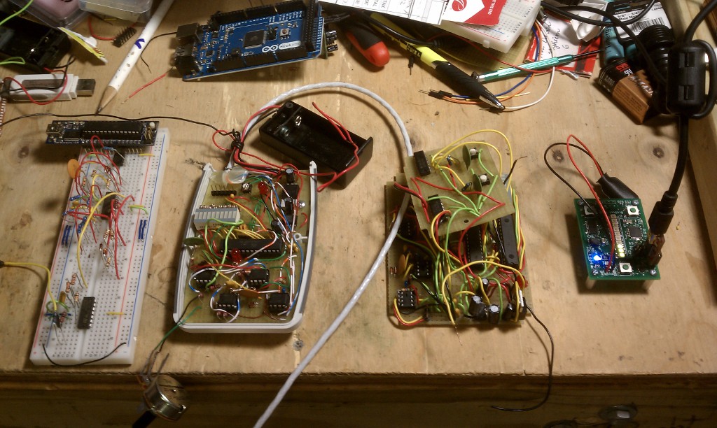 It looks janky as hell, right? But guess what ! It still worked. This is my usual progression when it comes designing and manufacturing circuits. This method has lots of issues like accidental shorts, which is why every time I look at someone's project, and see these gorgeous, well laid out, manufactured, smd soldered component boards, I get a little envious.
So why a development board? A lot of what I do involves body sensing, and with IoT in the mix, that makes for some interesting requirements.The interesting thing is when you do a search for wearable development boards, literally two things come up, and then my hackaday blog about making one. And to top it off, the two that come up are A.) Yet another watch, and B.) A board you can stick in a watch, and doesn't have the requirements that I want (wifi/bluetooth/lots of analog ports). So it makes sense for me to roll one out.
But I don't want to make yet another generic arduino esque board in the millieu. This one will be wearable, mesh capable, and talks to the cloud. And it has an educational purpose, and serves as the foundation for other projects, like helping my researcher friend studying Rett syndrome, a rare, neurological degenerative disorder.
So the first thing I do whenever I start a new project, is I figure out what it needs to do first. These are my requirements.
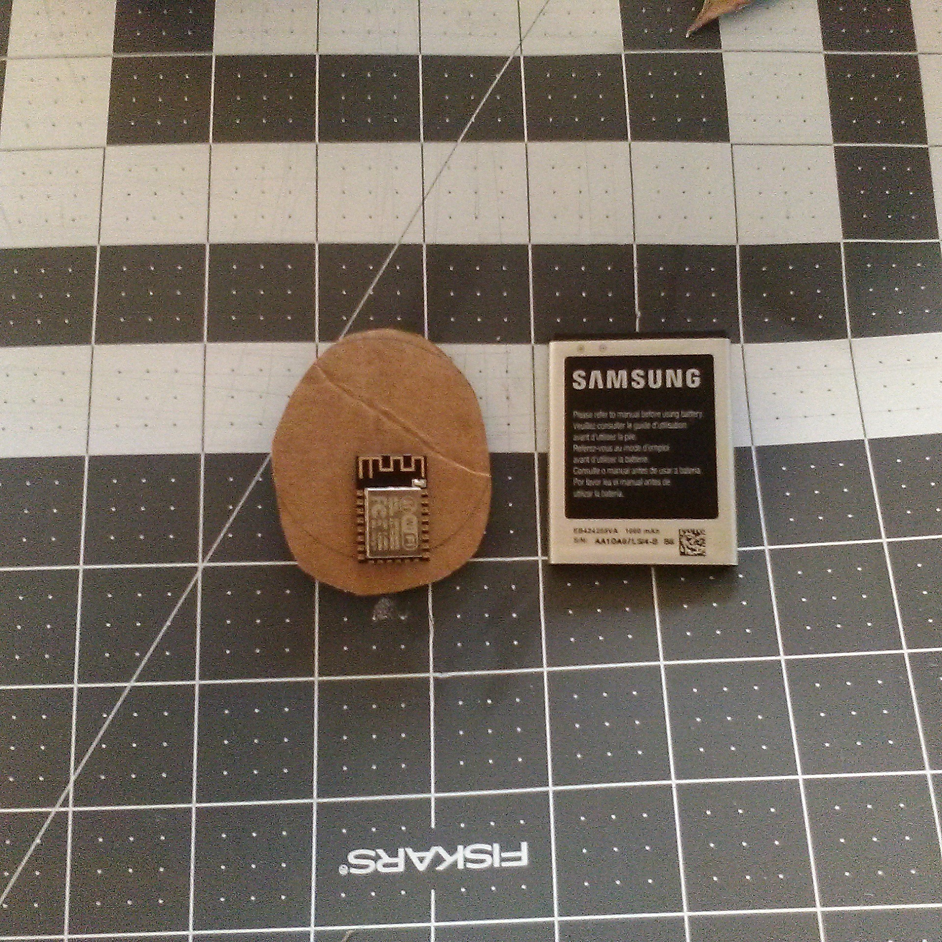
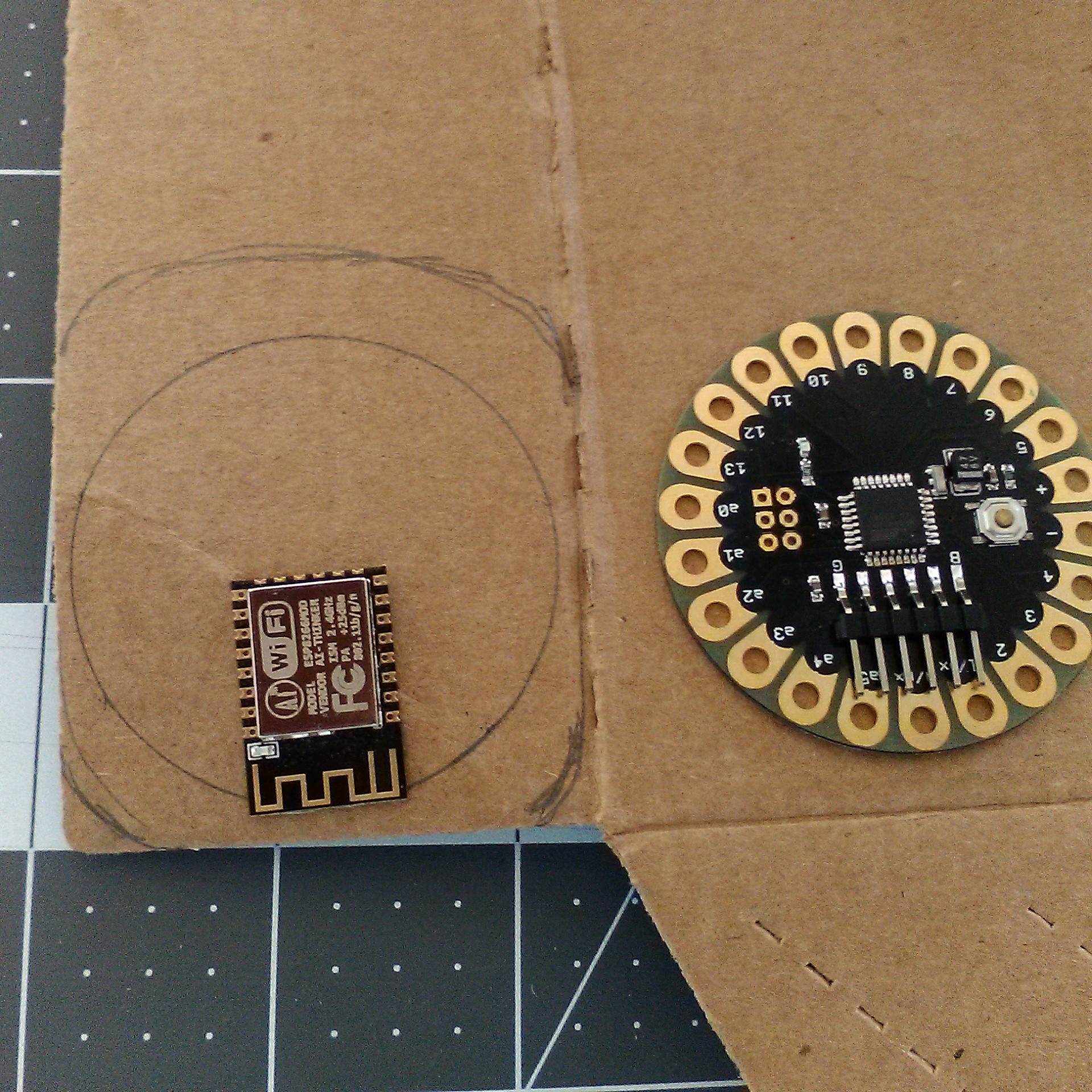
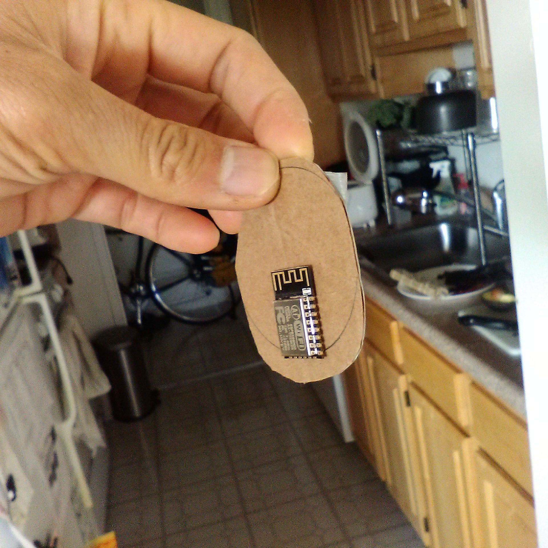
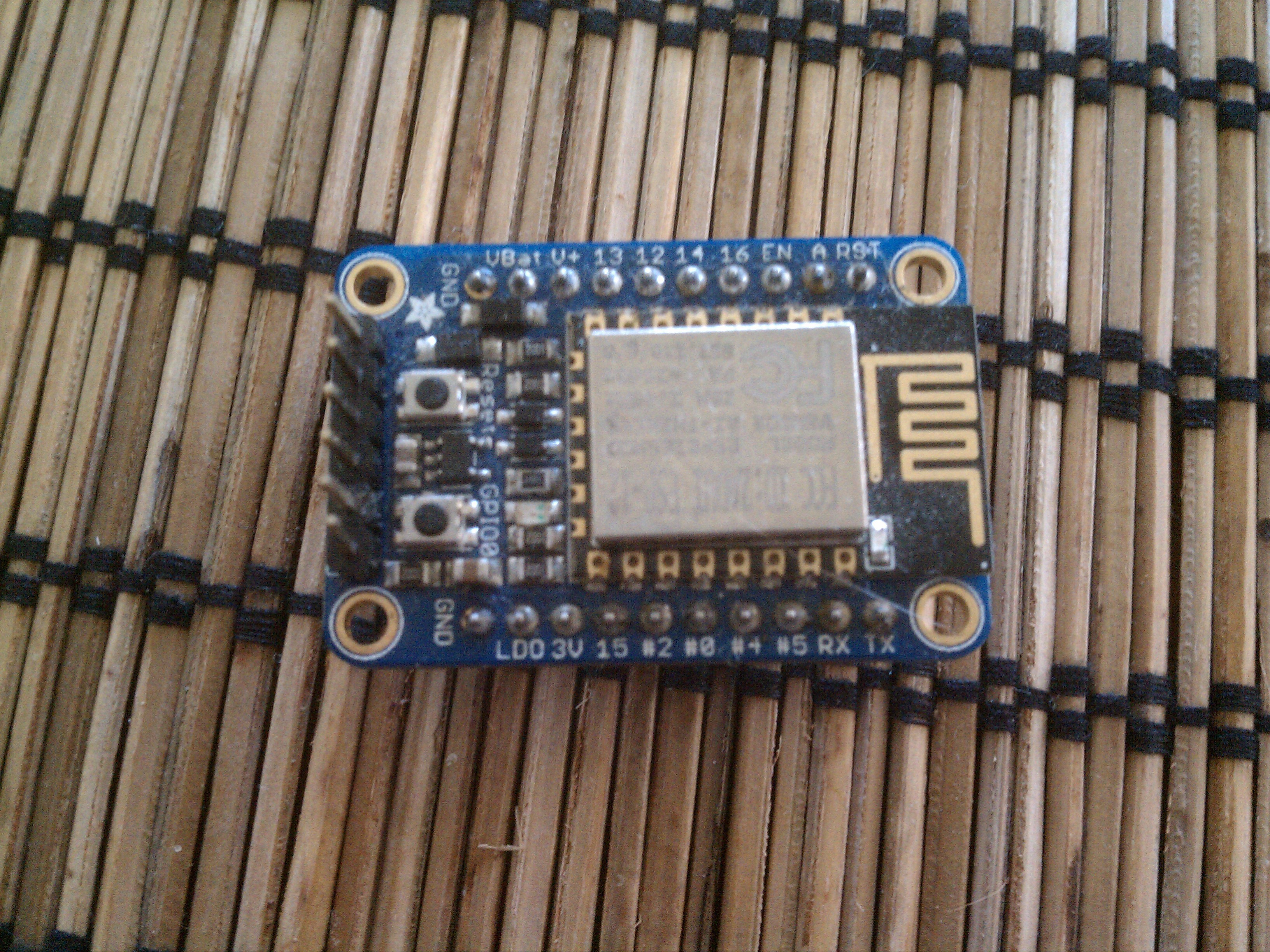
- It needs to be wifi/bluetooth capable. Since I'm very well versed in Arduino's java like syntax, and C++, I went with Espressif's offerings, the ESP8266 and ESP32. Since the ESP32 isn't yet mature Arduino wise for most people, I'm gonna start first with the ESP8266.
- Arduino compatible. I like having tons of libraries available, and a massive community to support. I don't like waiting to call an engineer on the phone to get answers.
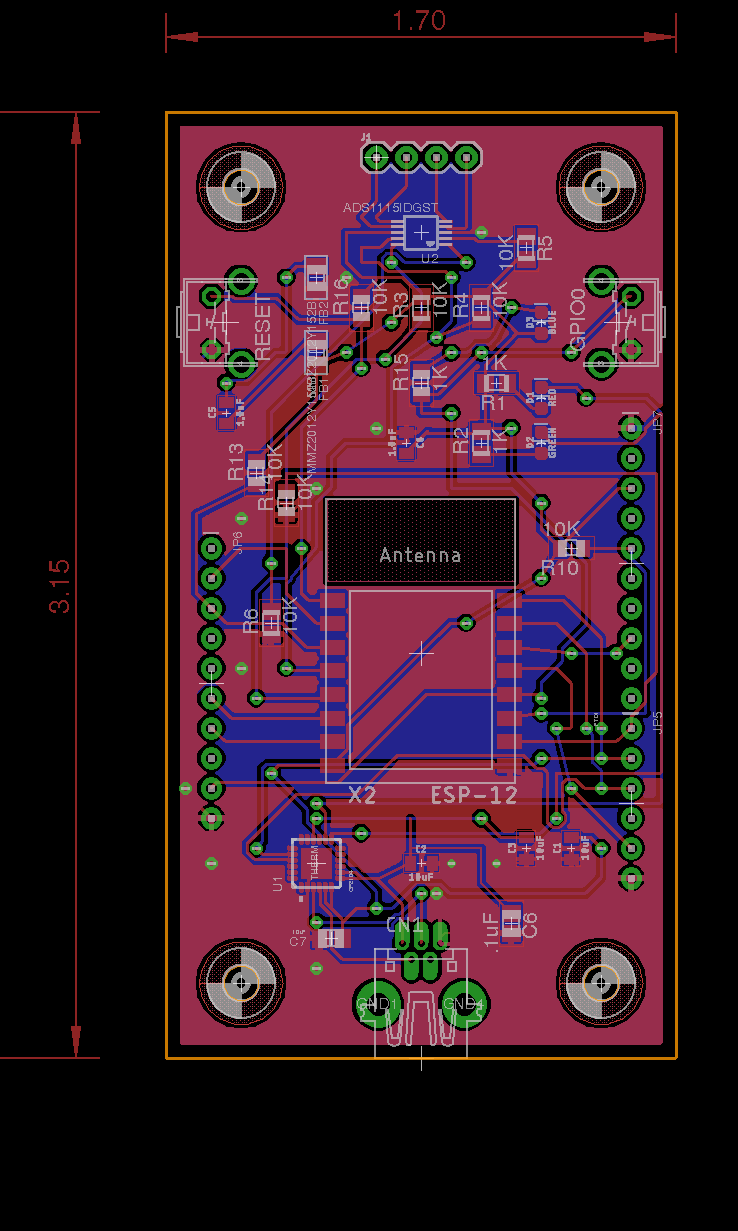
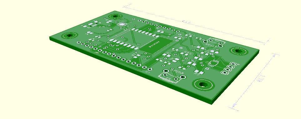
- The problem with the ESP8266 is it has only one analog port. Which is fine for all the freaks out there that are into blinky lights, because for blinky lights all you need is GPIO, and most of the time you only need one. But I do a lot of analog sensing. I'm also not into blinky lights (I'm into FIRE. Yes, I'm that kind of freak.)
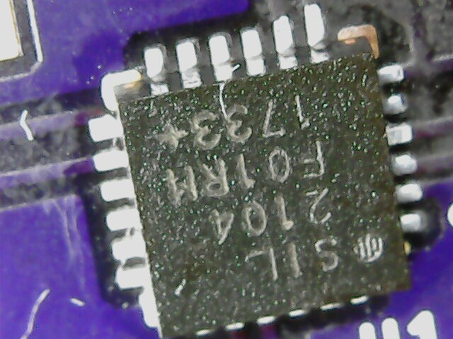
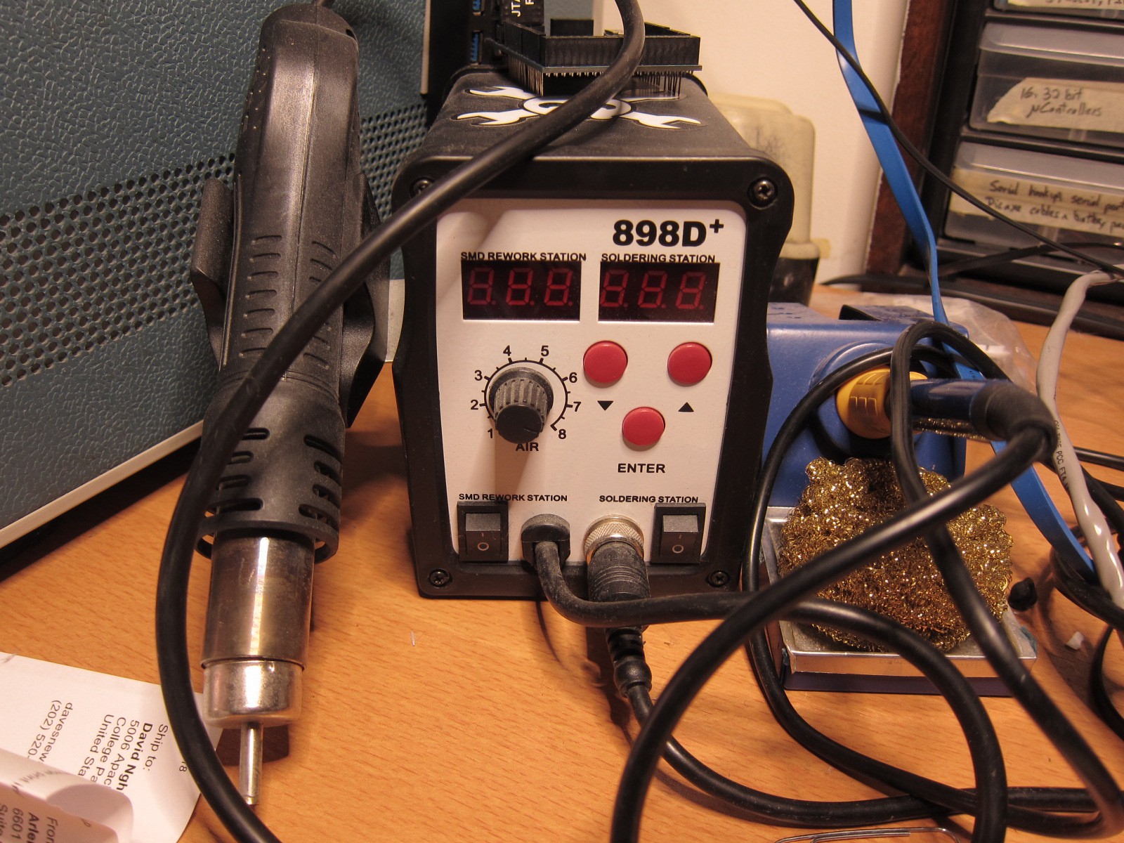
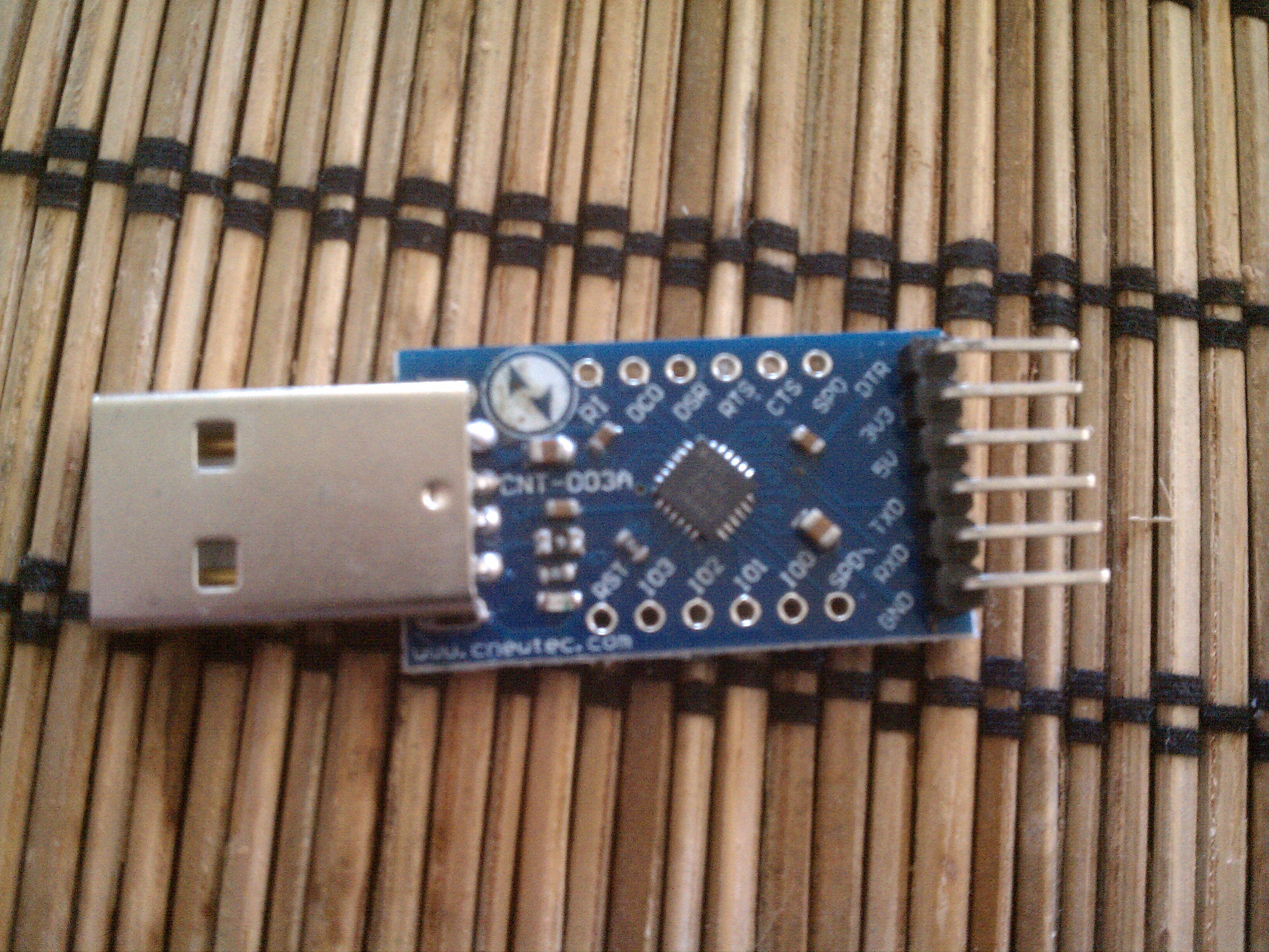
So I'm adding an ADC chip. - I'm tired of using my USB to TTL converter port and loose wires to the ESP8266, so I'm incorporating a USB to TTL converter chip, like the CP2104. Which means it'll have a straight up micro USB port. Hell yes!
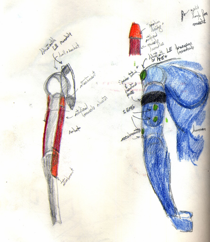
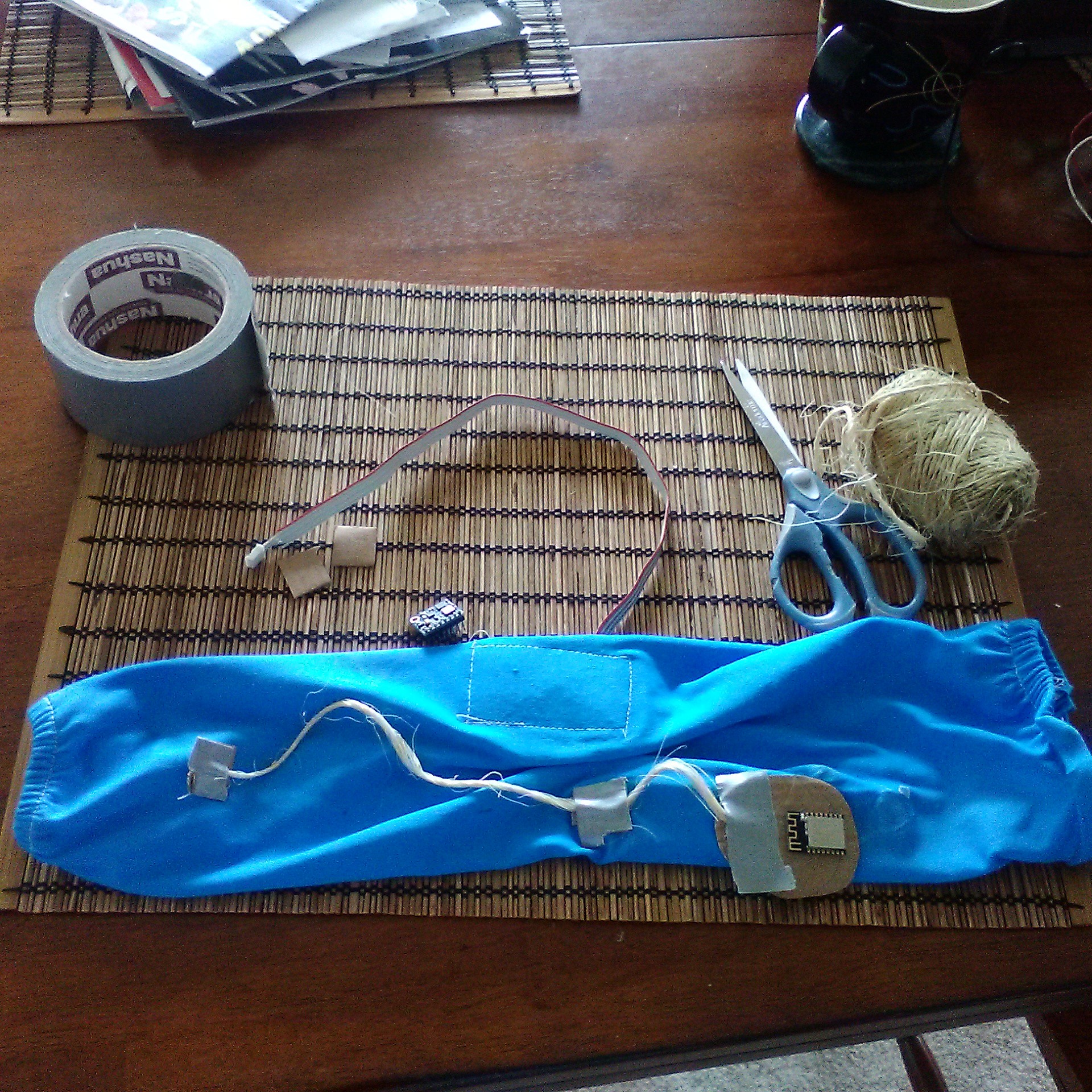
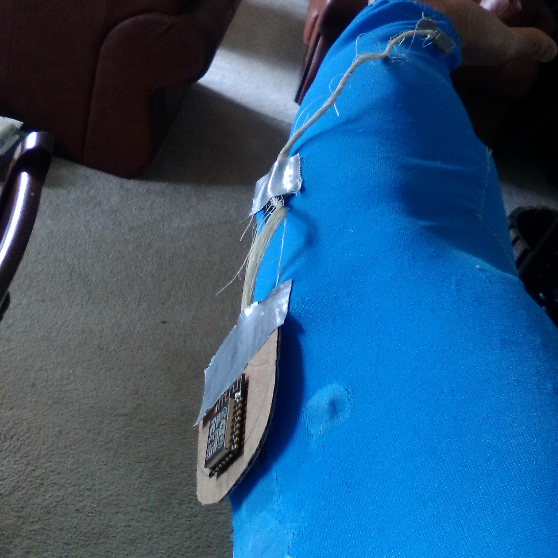
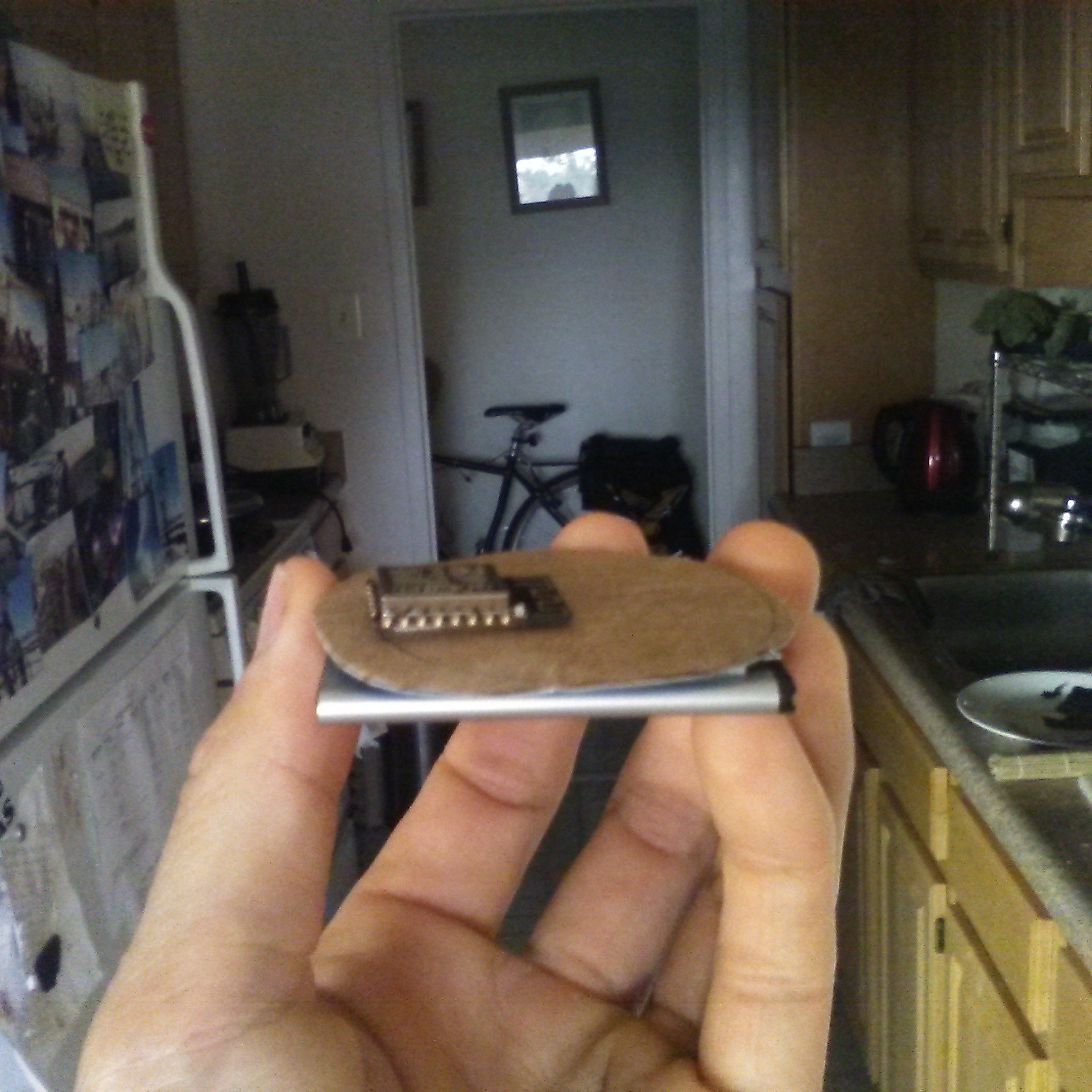
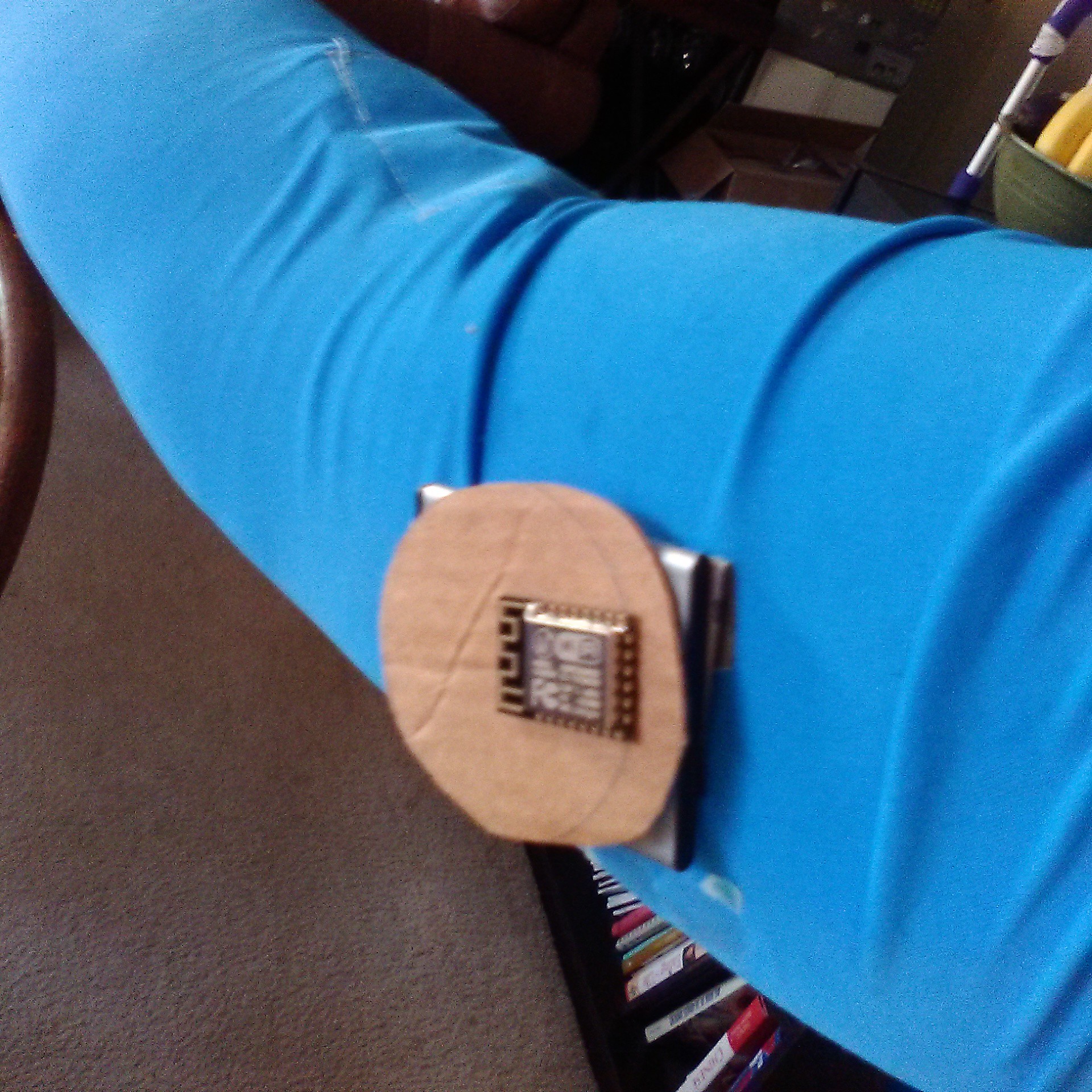
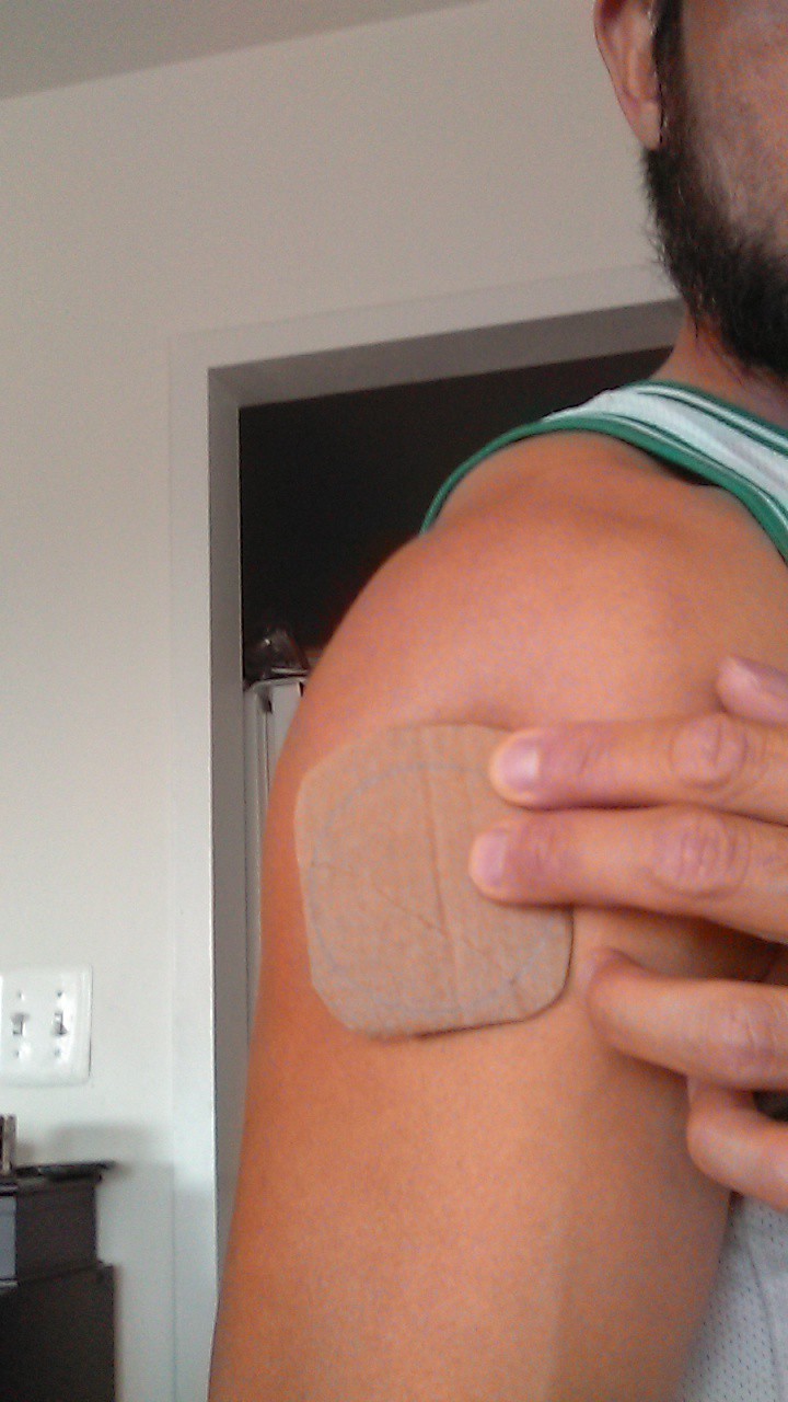
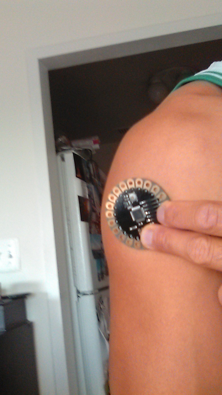
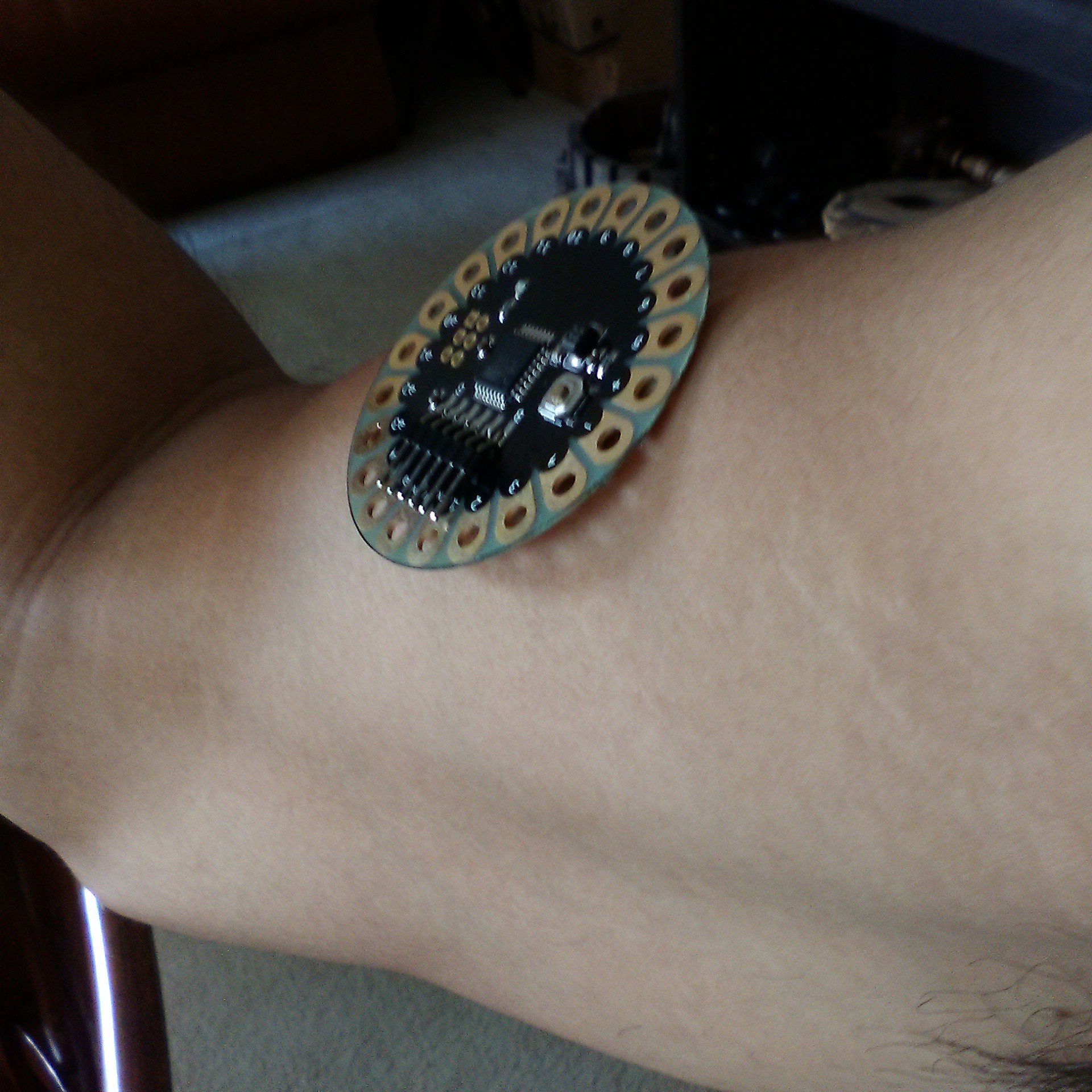
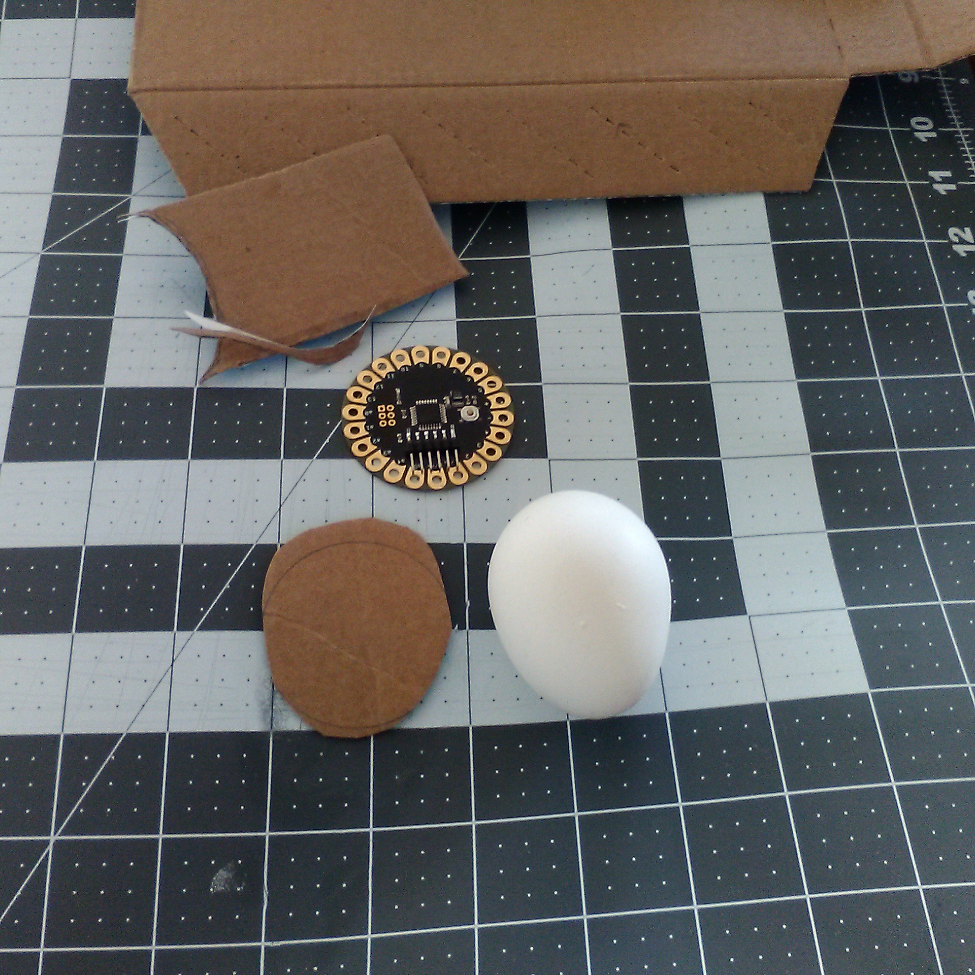
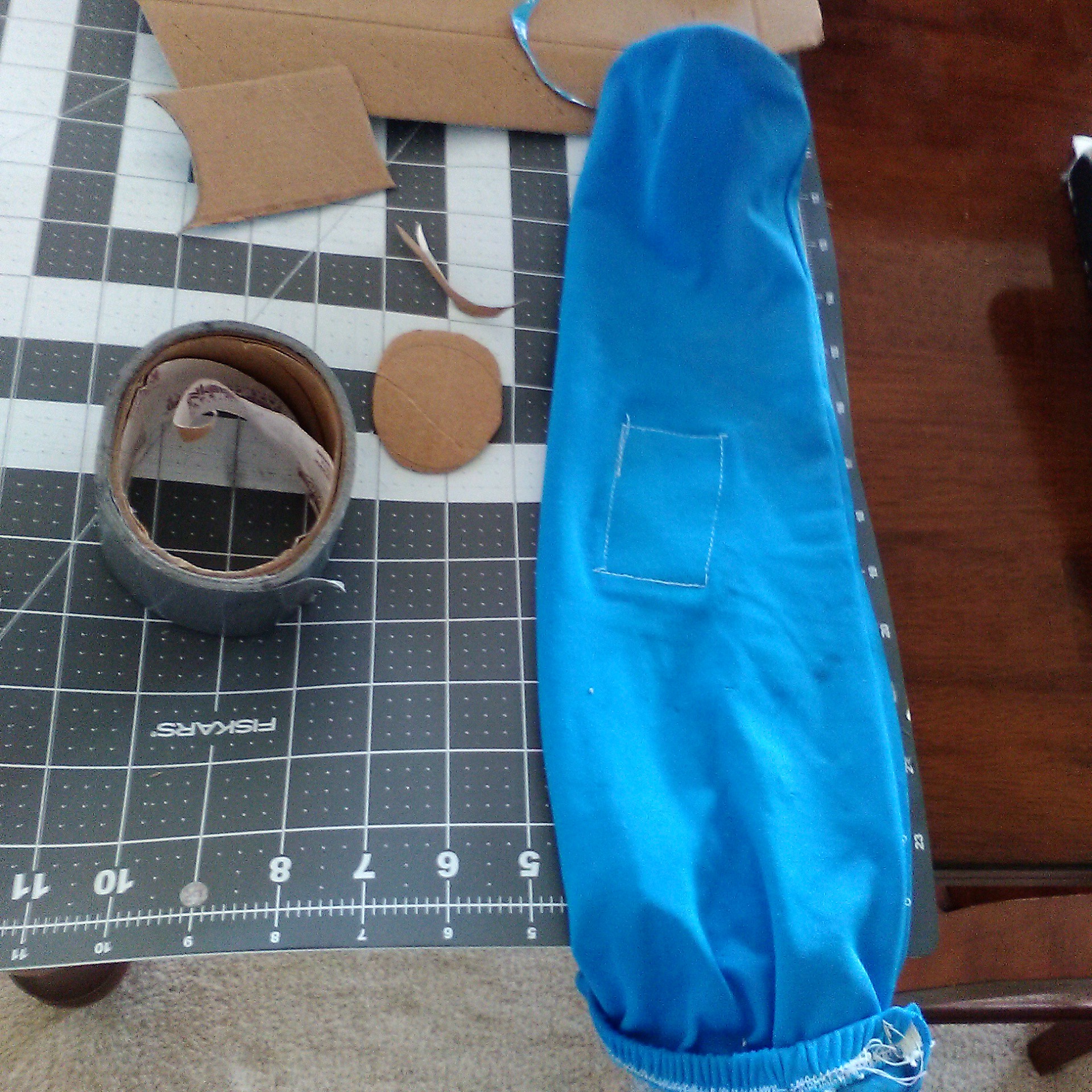
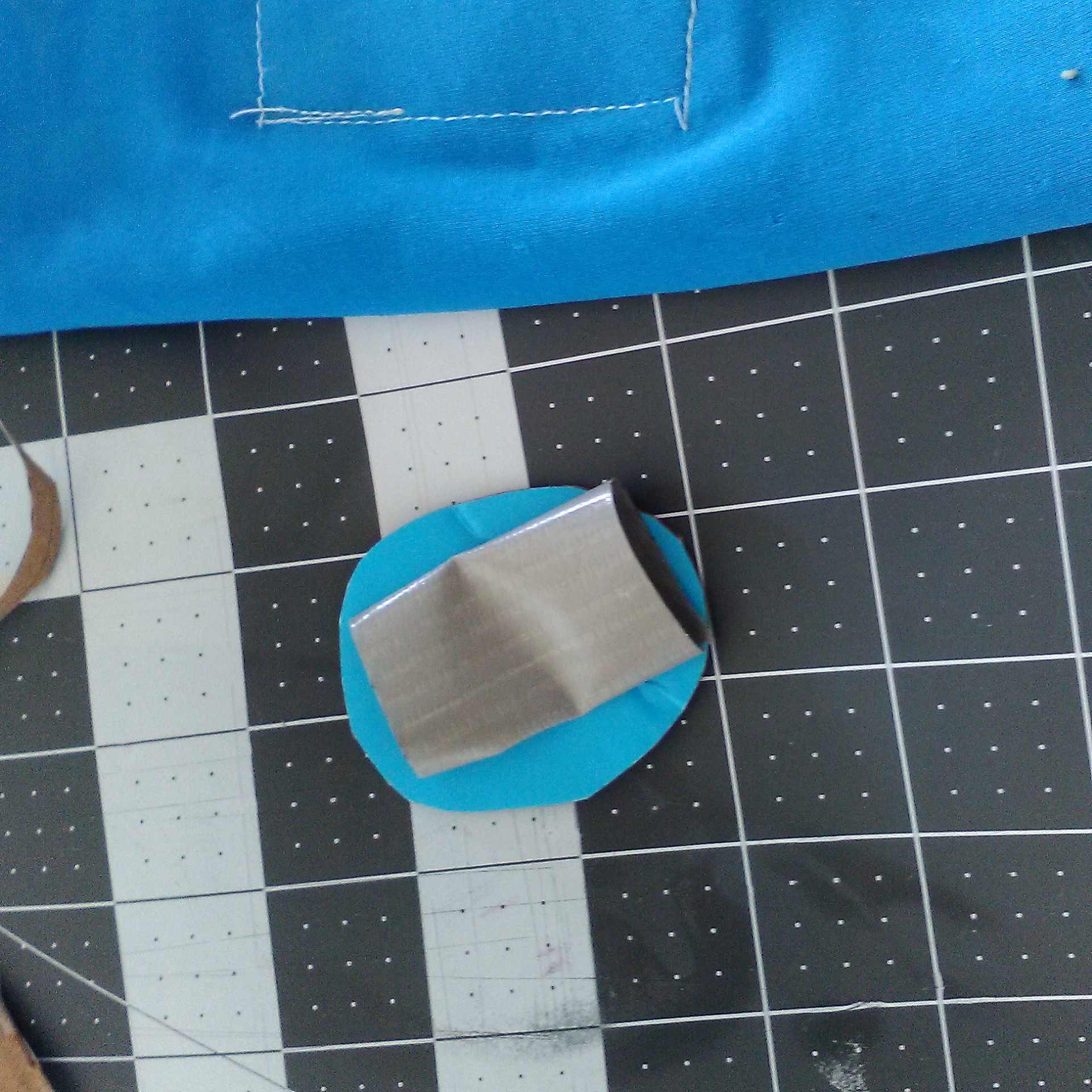
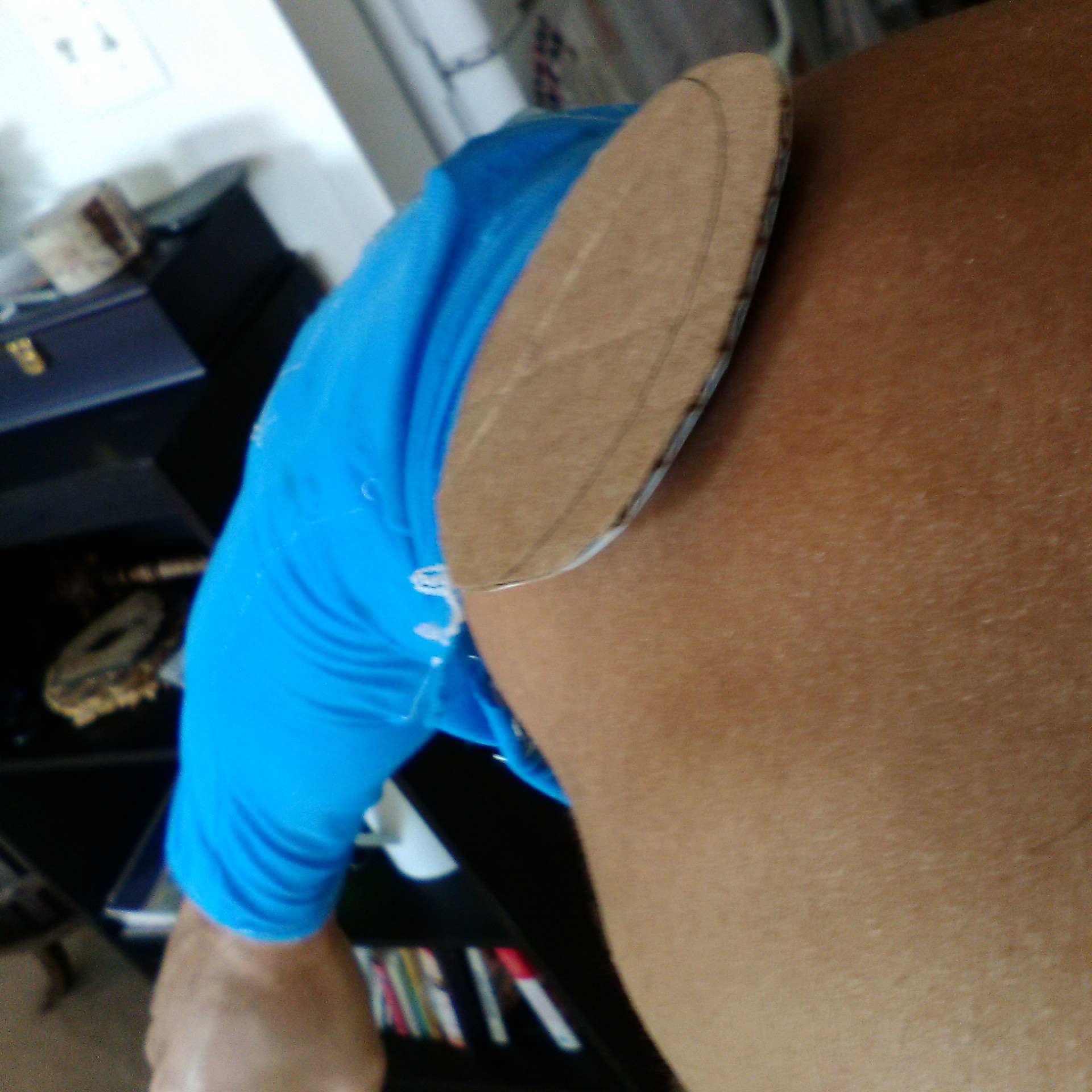
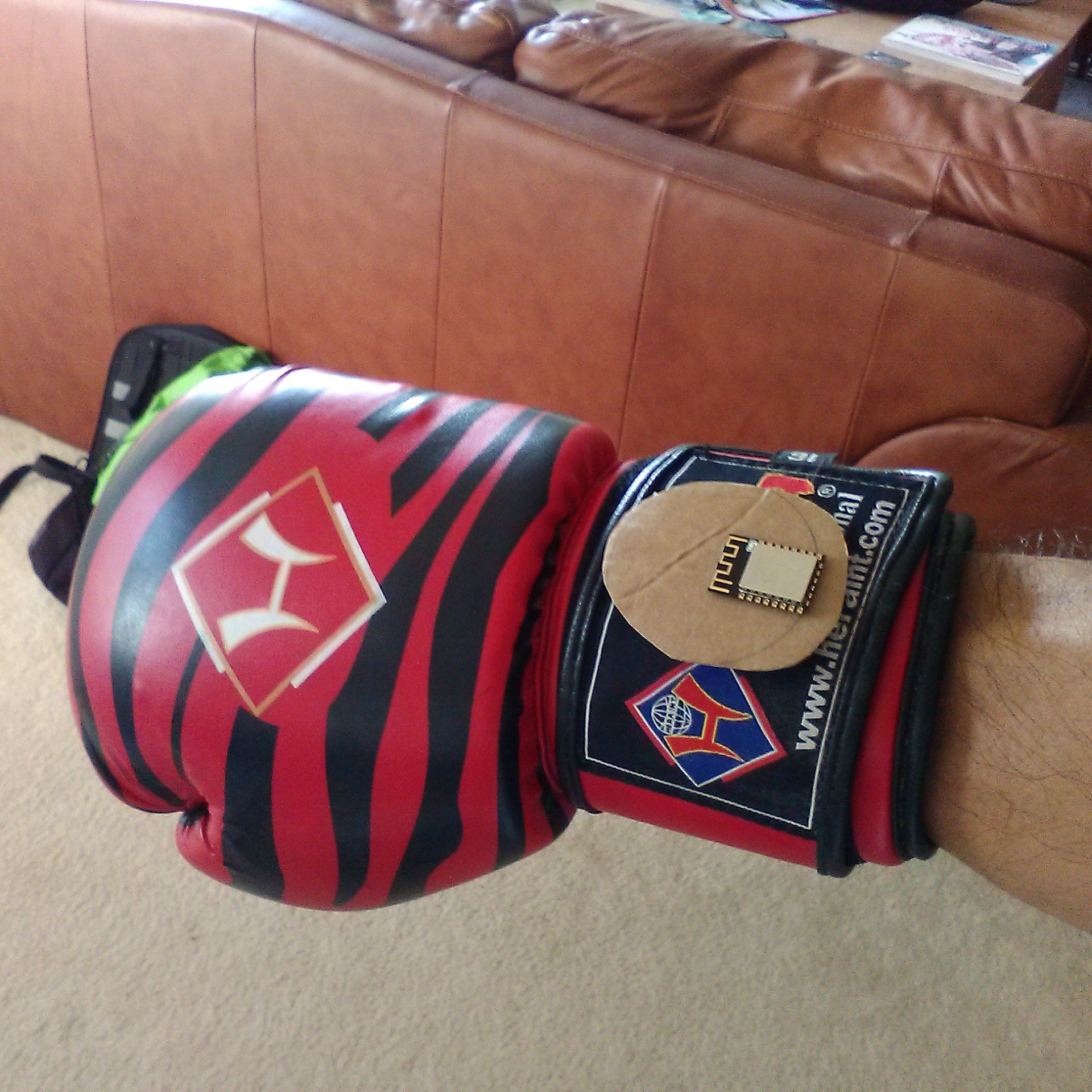
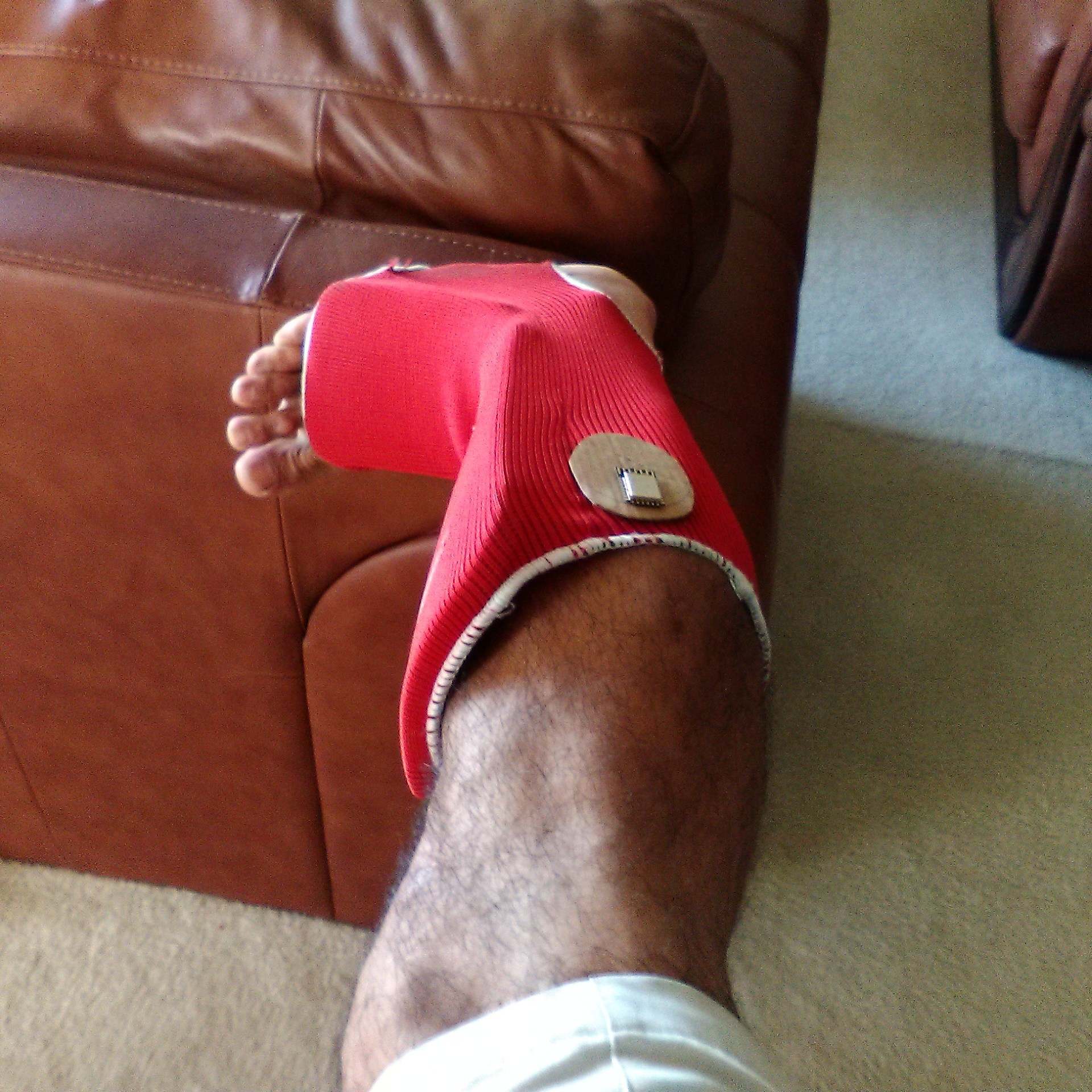
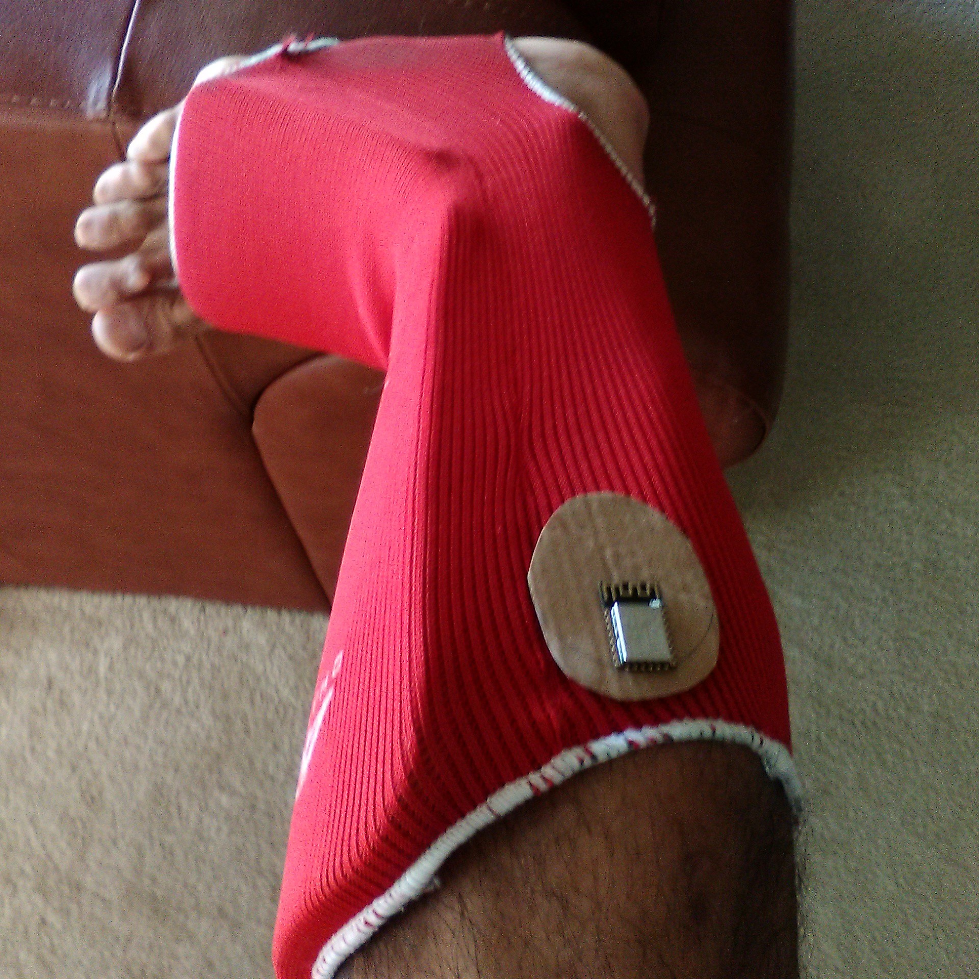
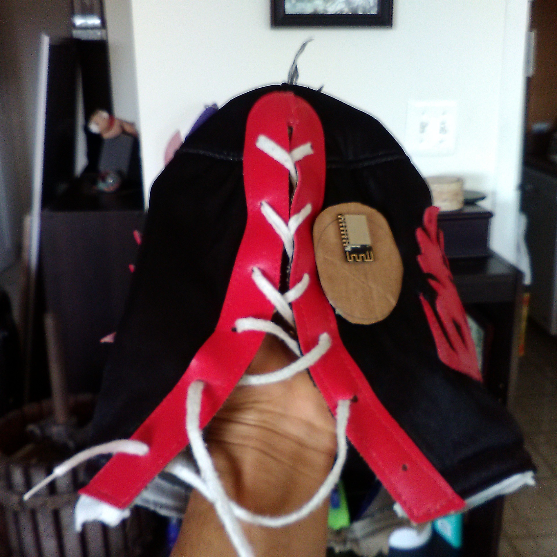
- I want this to be wearable. If you look at my SEMG sensor, it's something you wear on your clothing. So I'm looking at putting it into a wearable, and sew-able form factor. Or at least velcro-able
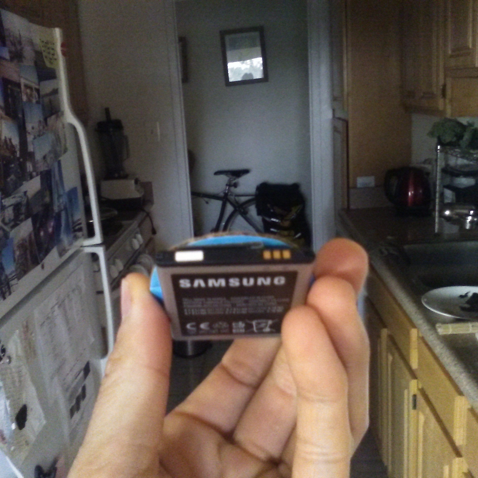
- It needs to be powered by 3.3V, with as little power requirements as possible.
- Have a usb charger control circuit that can connect to a lithium ion battery pack, because that's also been a pain in the ass to replace AAA batteries every time.
- Unlike the lilypad, which is also my inspiration, I'm not a fan of sewing wires into clothing. Mainly because I suck at sewing, though you wouldn't know it when you look at some of my wearables (Thanks Mom!!!). So, it's going to have cable pins with locks on them. I want to dasiy chain sensors across the body to the board, which means I2C is ideal, SPI also works, BUT you have to becareful with some analog applications because ribbon cables are notoriously noisy at picking up random signals.
- Use...

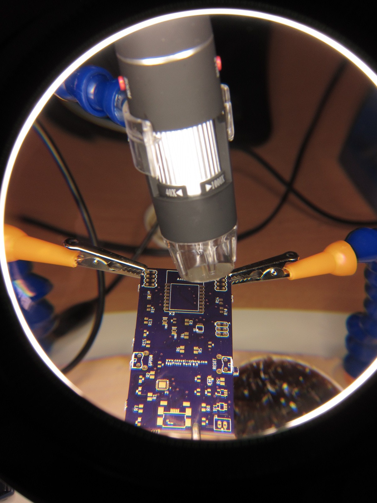
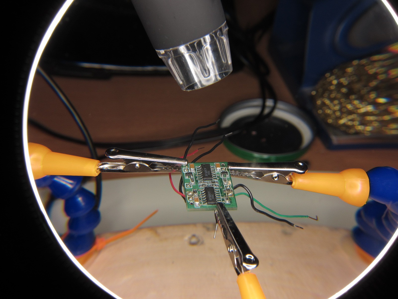
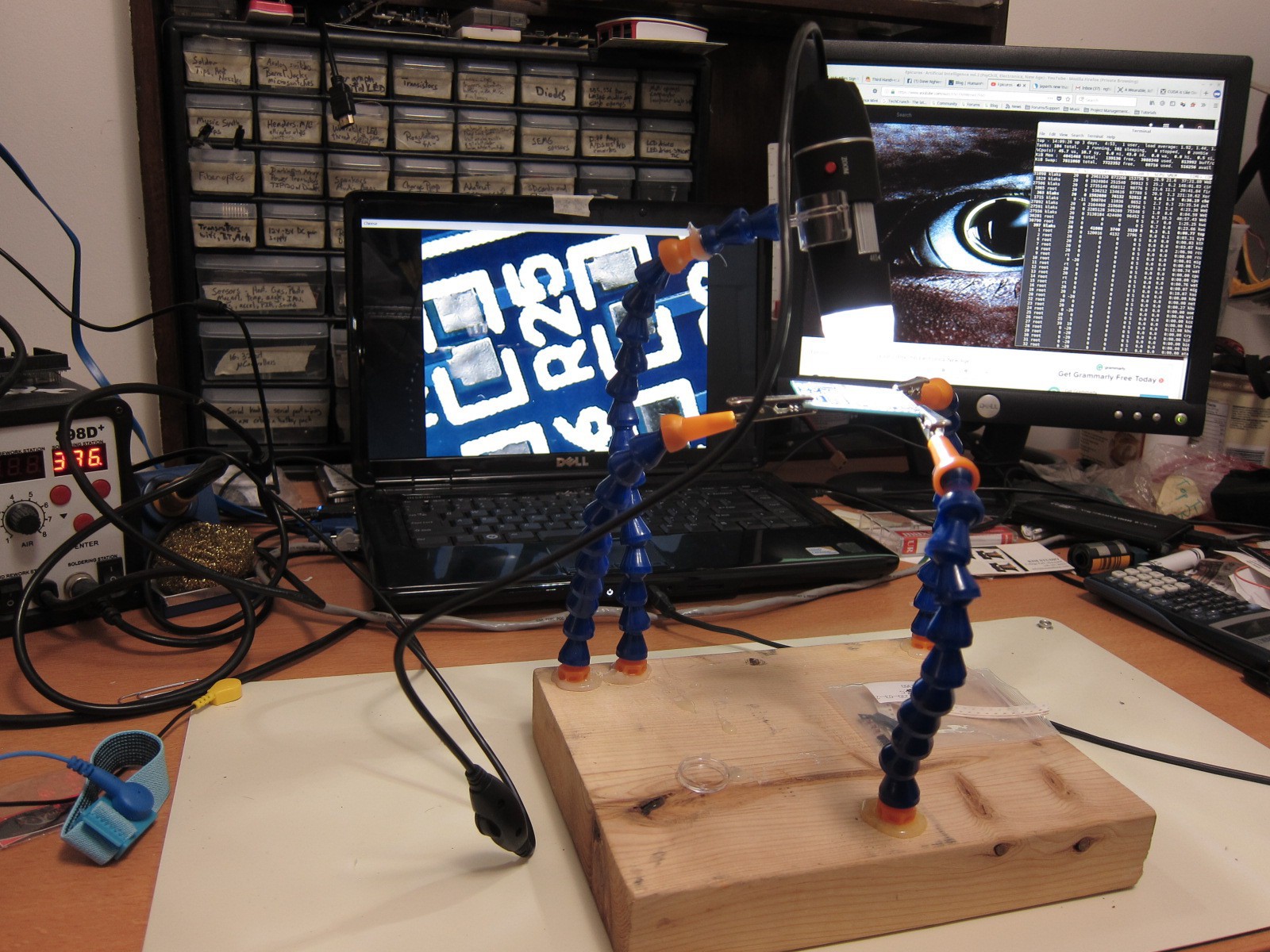
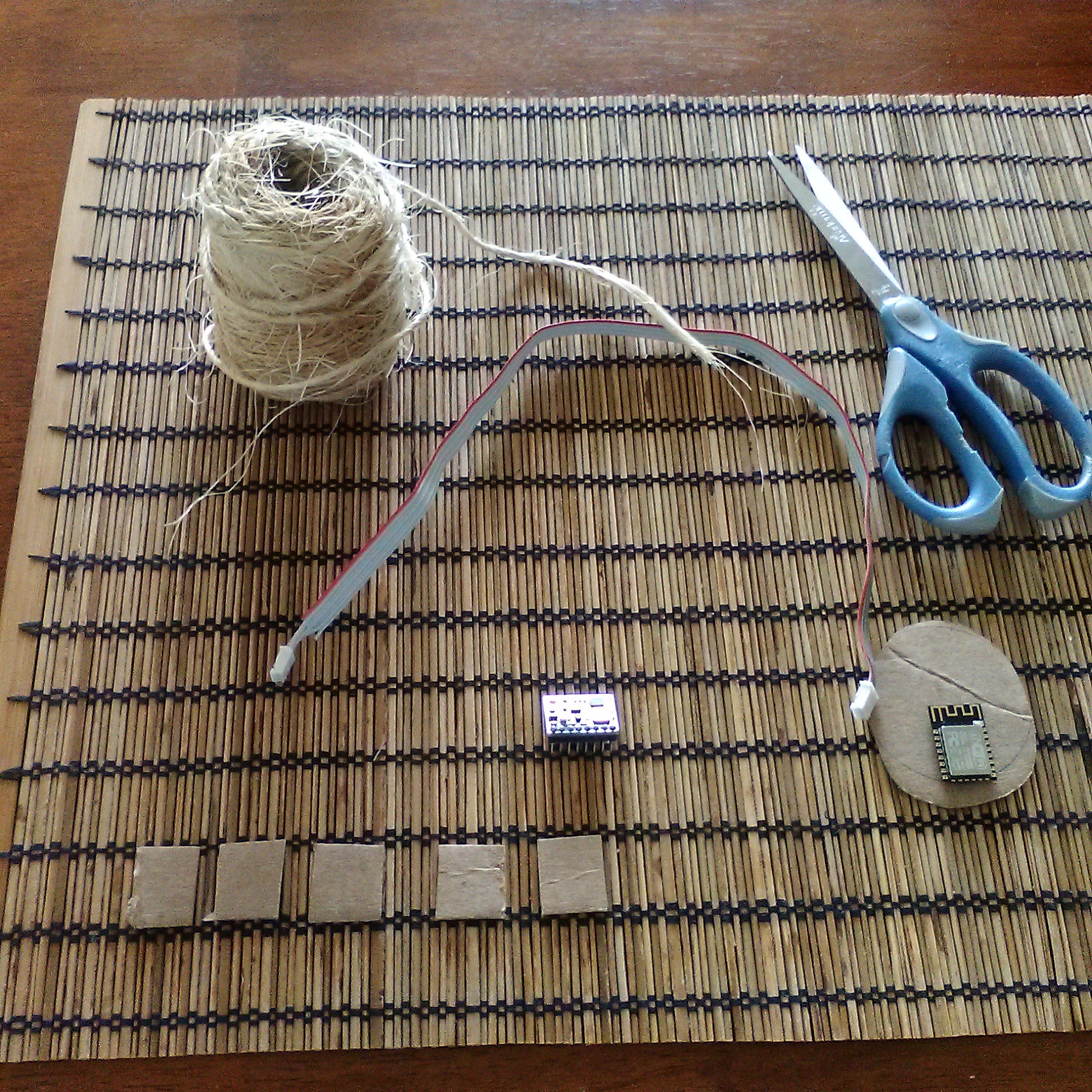
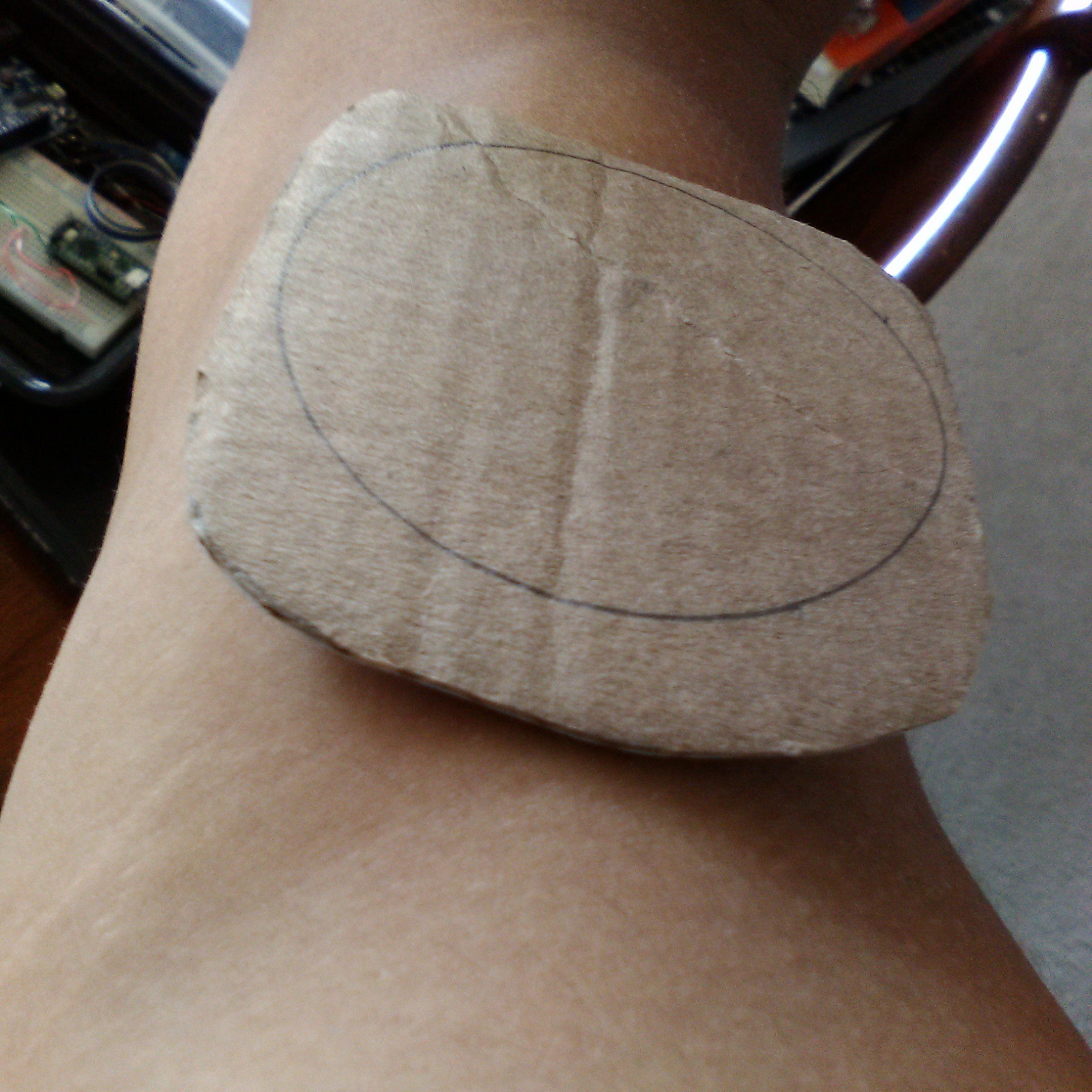
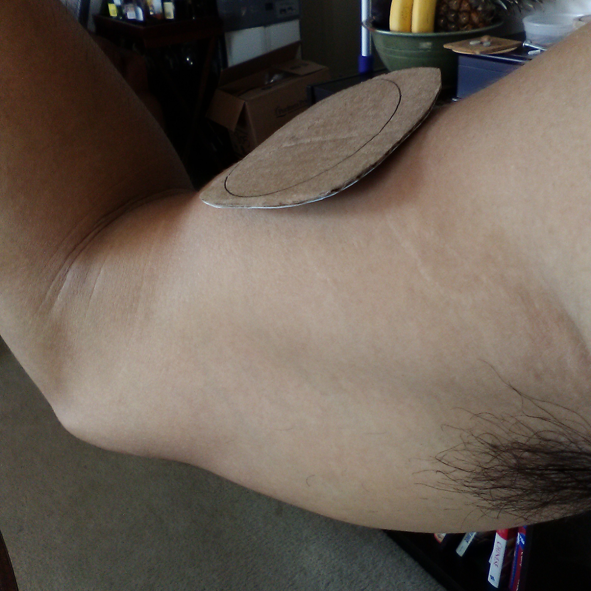
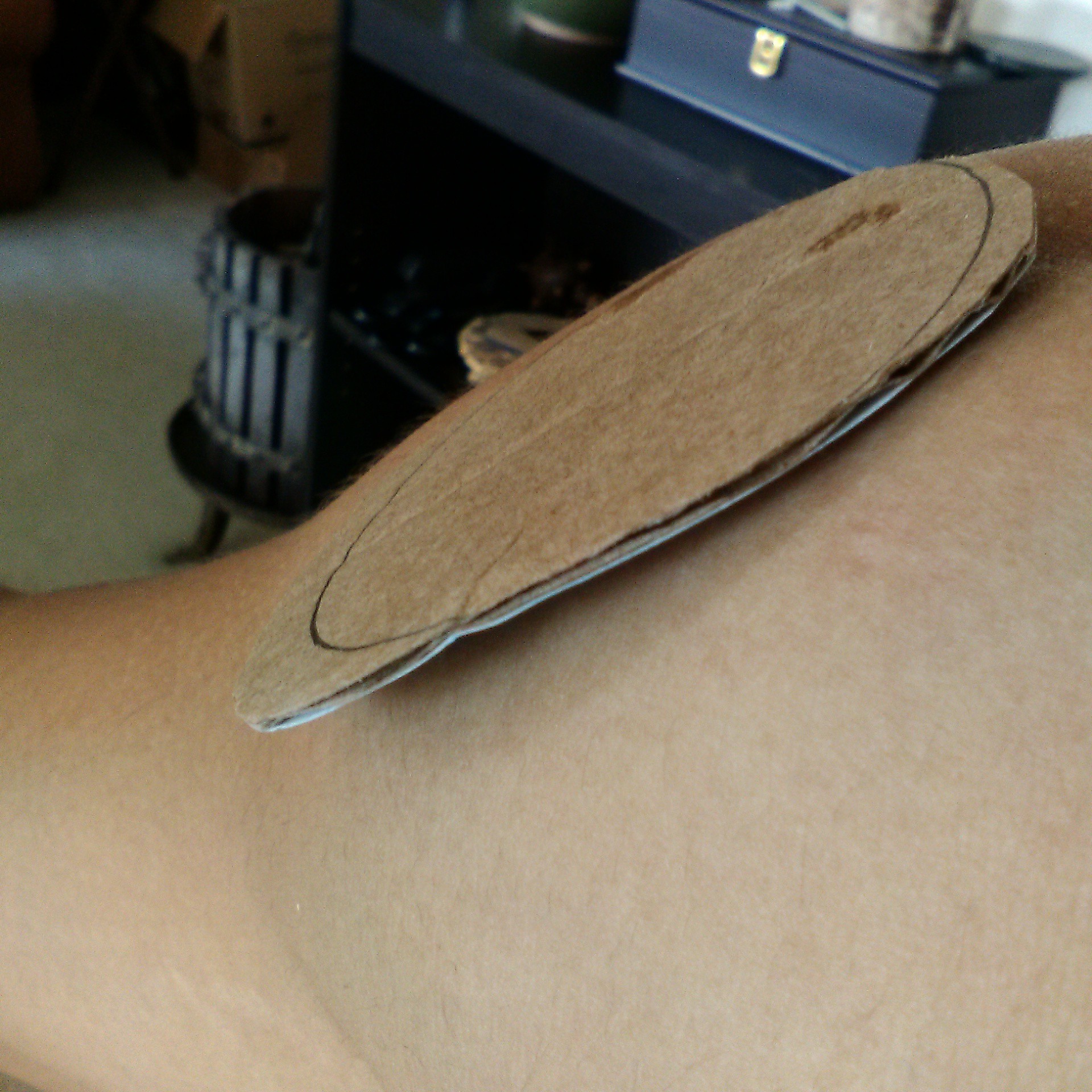
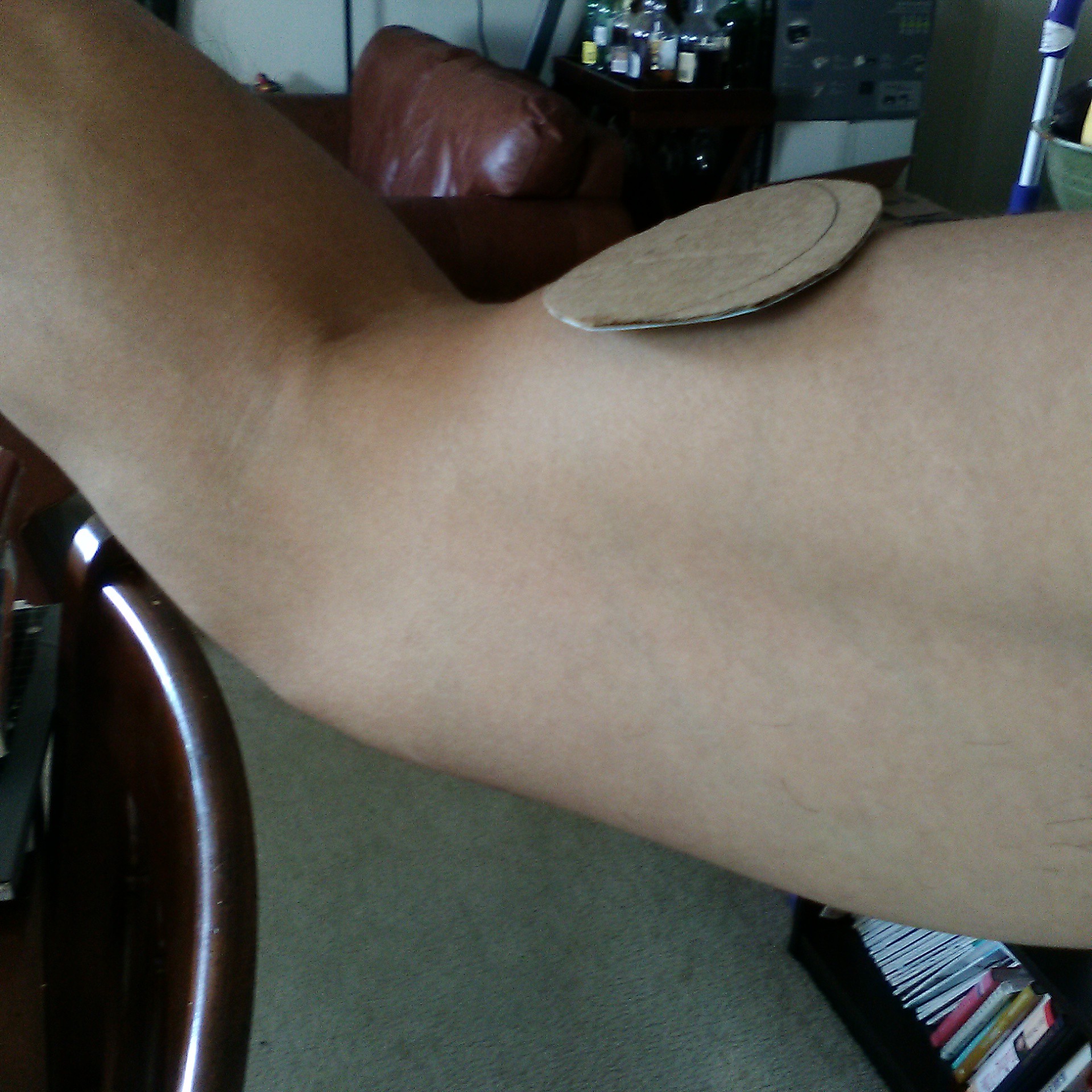
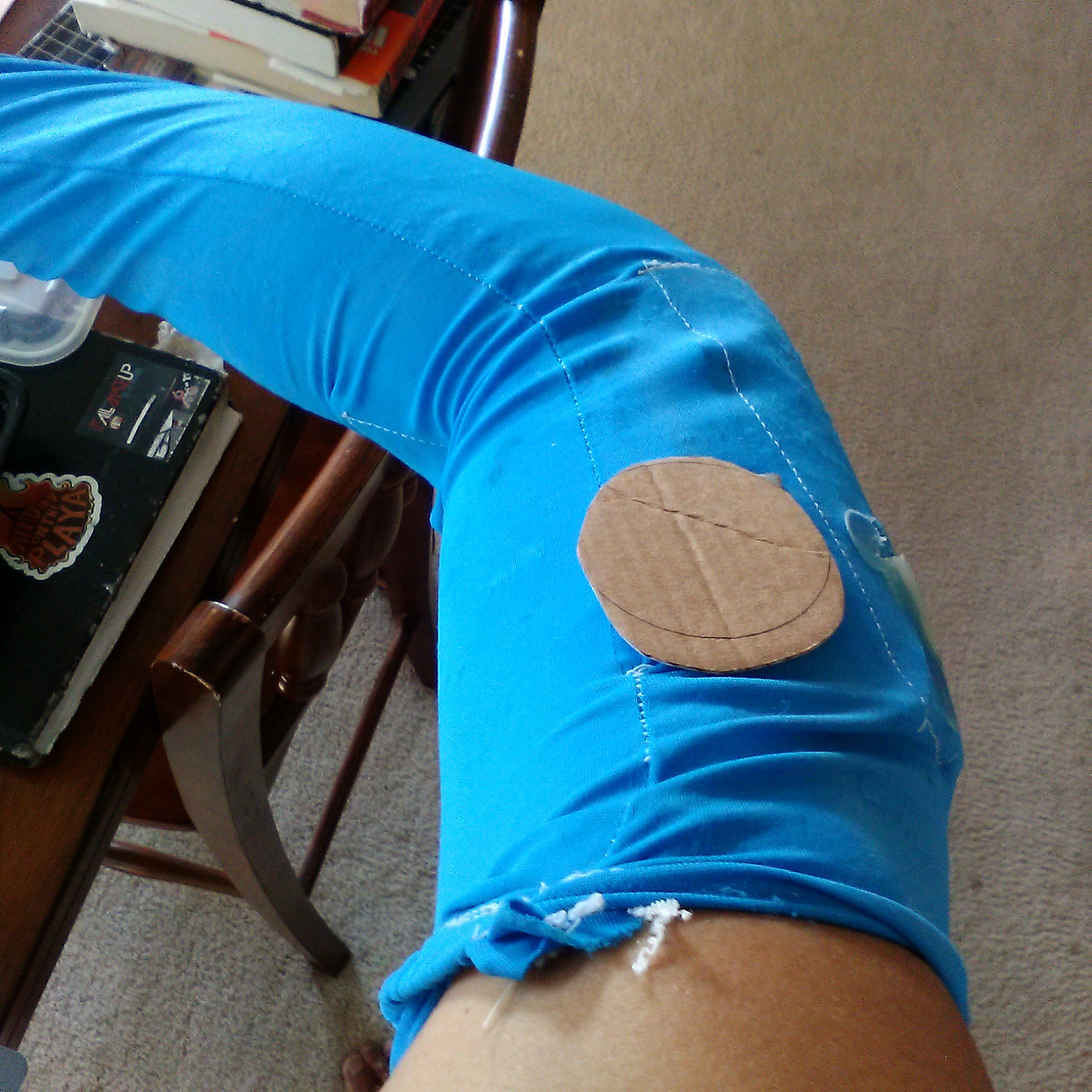
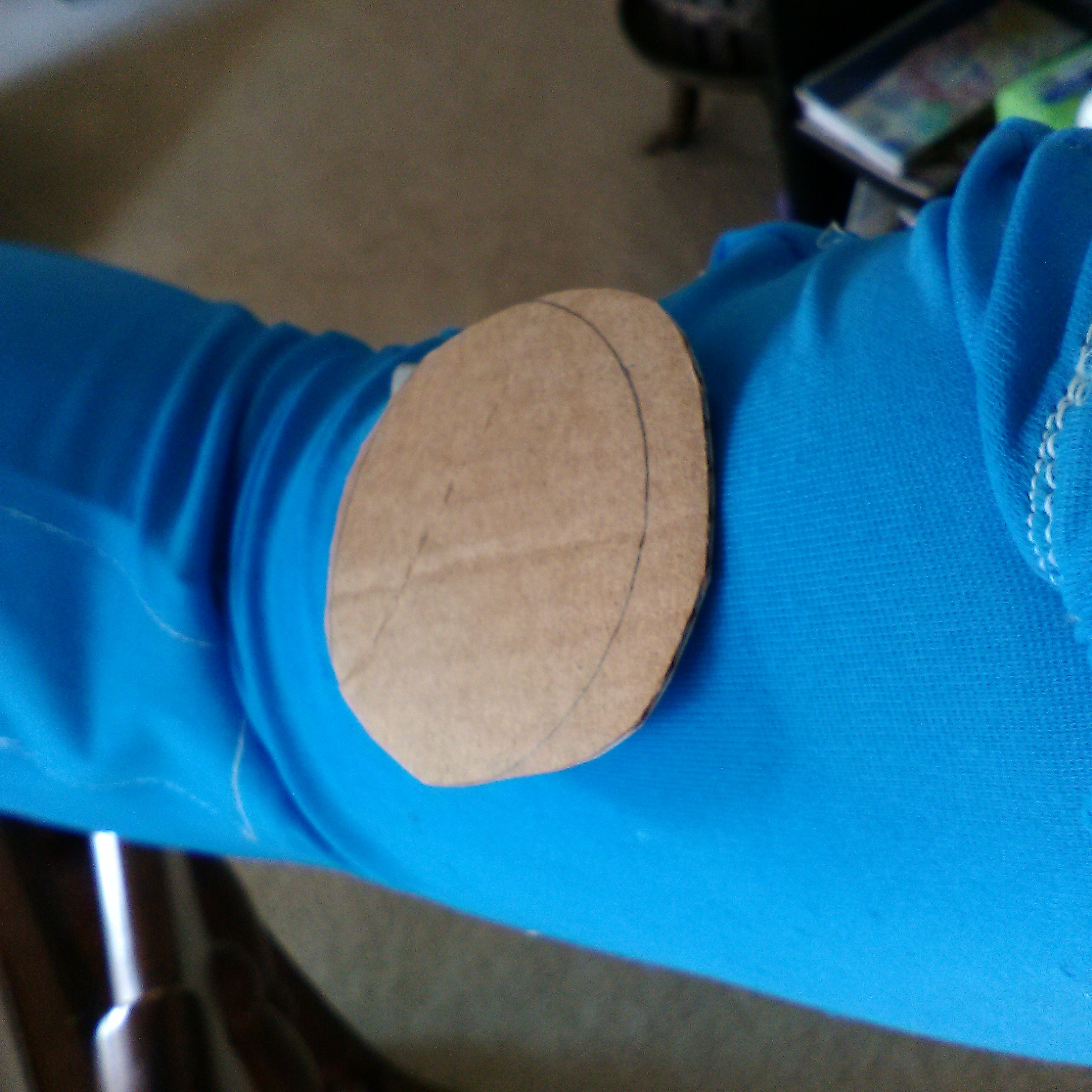
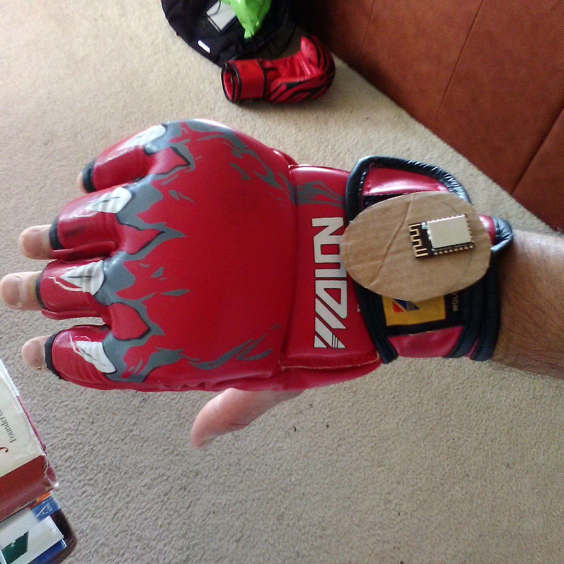
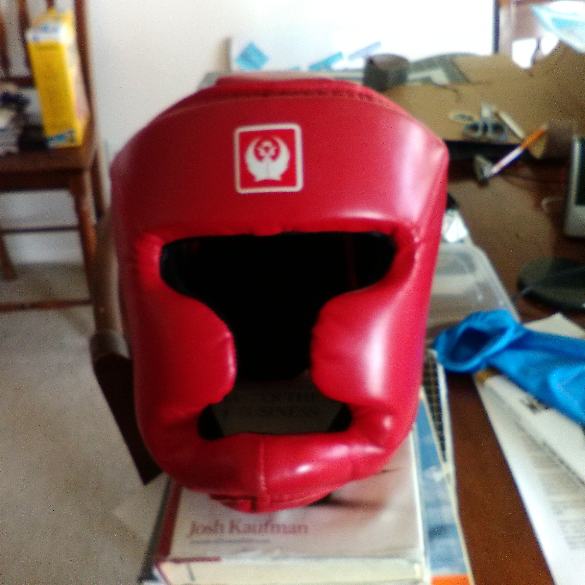
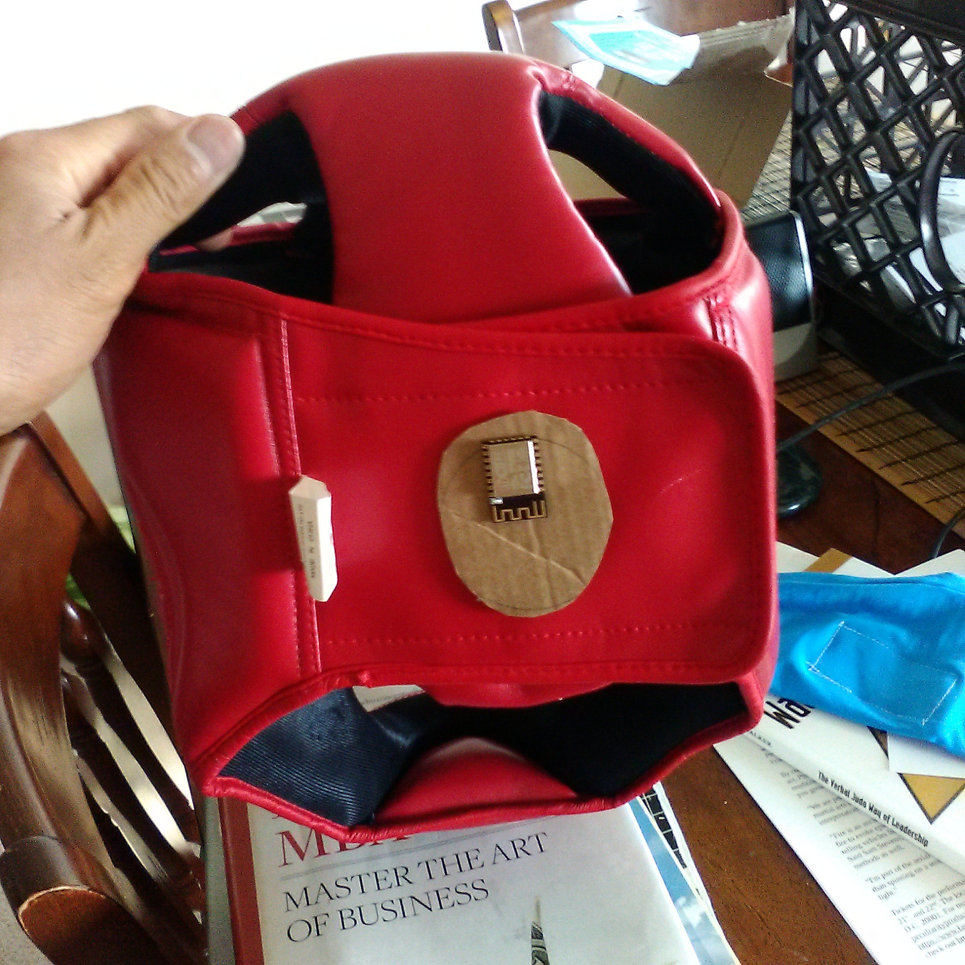
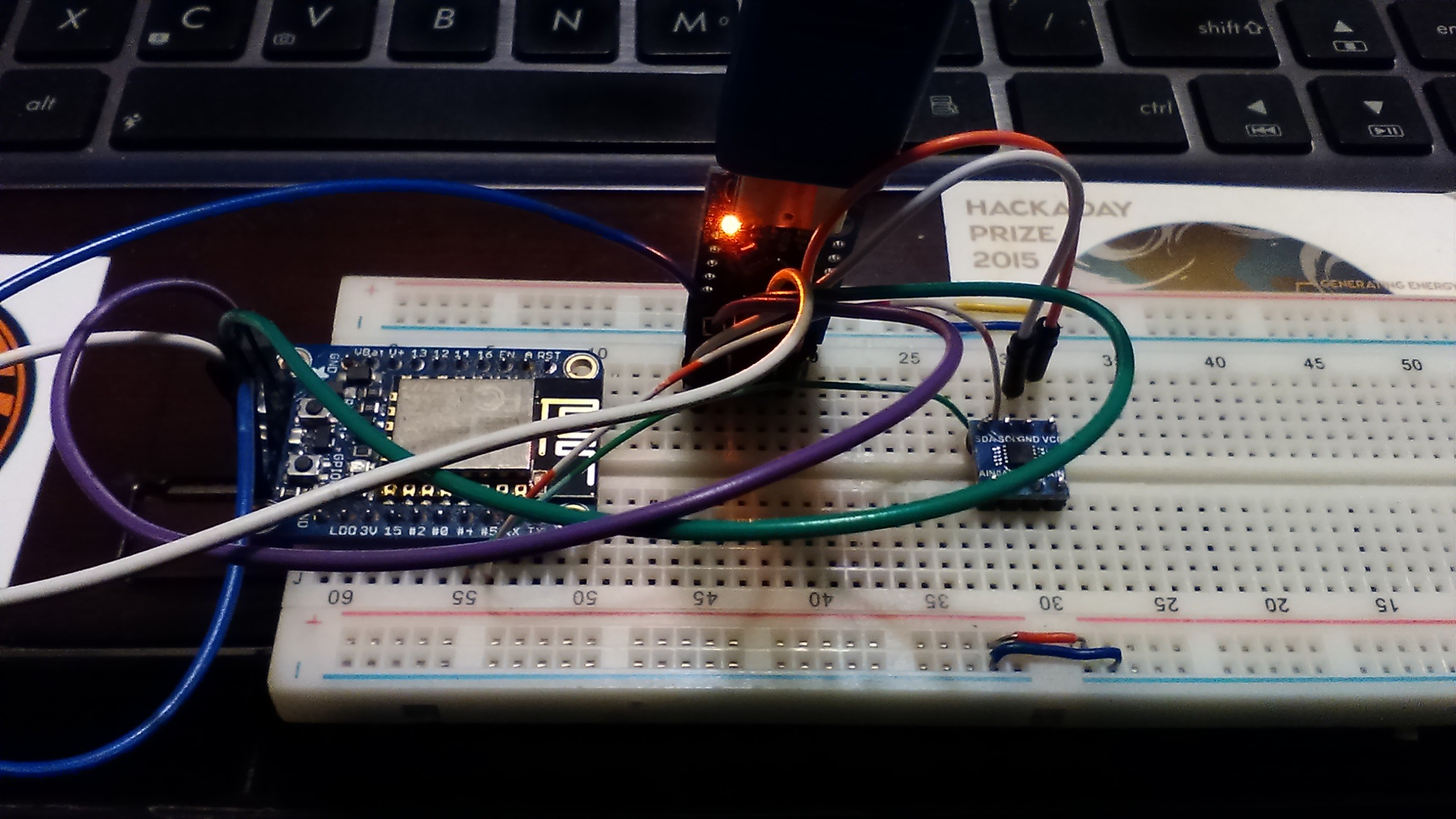
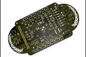
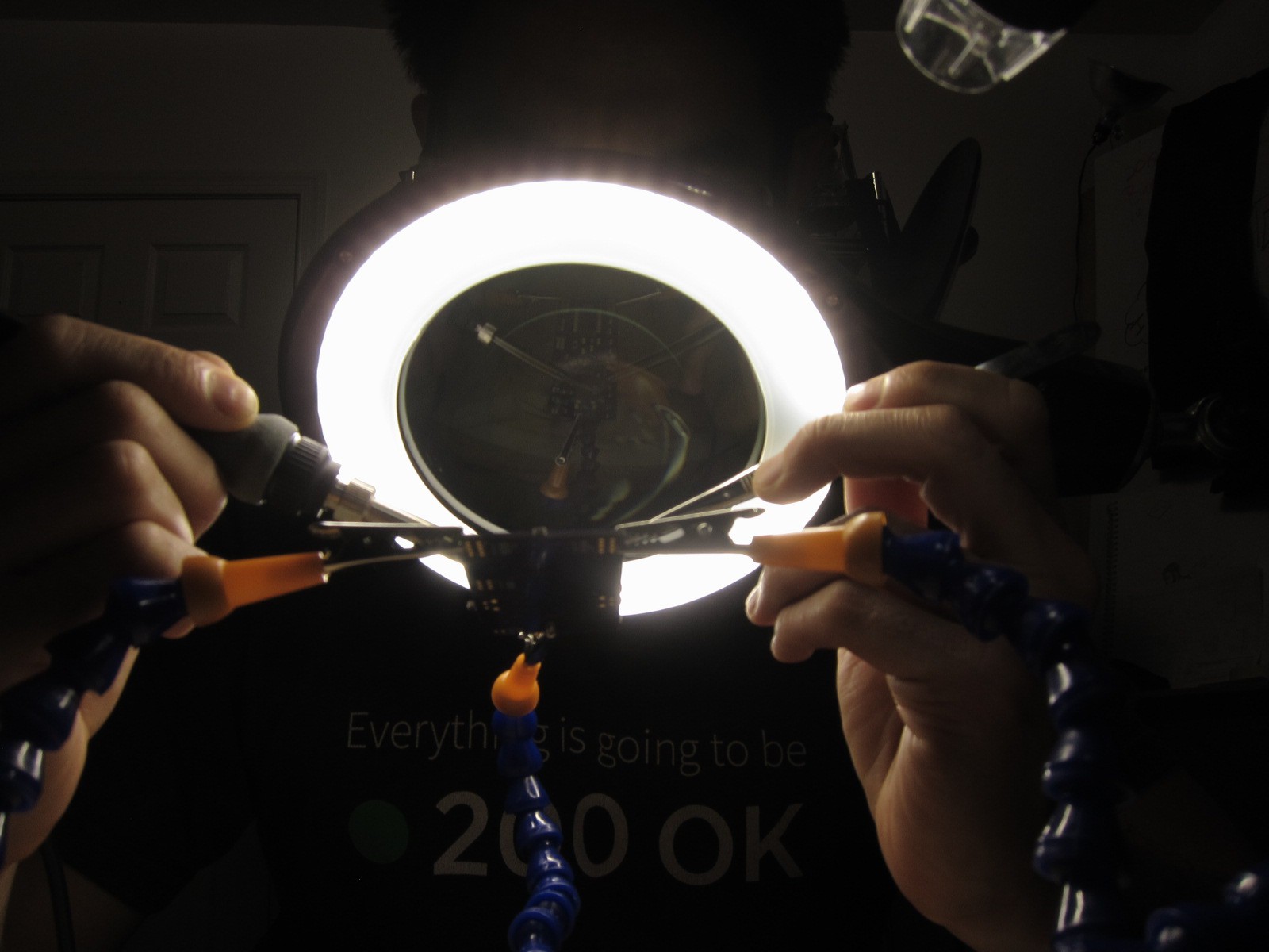 Hard at work manifesting a crazy technology idea. On to next week when I get the right parts in. Stay tuned!
 Replicating a basic neural network - because let's face it, I'm not going to recreate the human neural net system in its entirety, at least not presently - doesn't involve a lot of neurons. For that, in the beginning I'll integrate something like tensor flow or IBM's Watson on the backend. But what I really want to build and integrate is a wearable neural network interface with the wearable IoT device. So, I'm starting off with the Neuromem Biomorphic BrainCard. Which unfortuately isn't being made anymore. I lucked out because I've been following hardware neural networks since the 1990's, starting with the
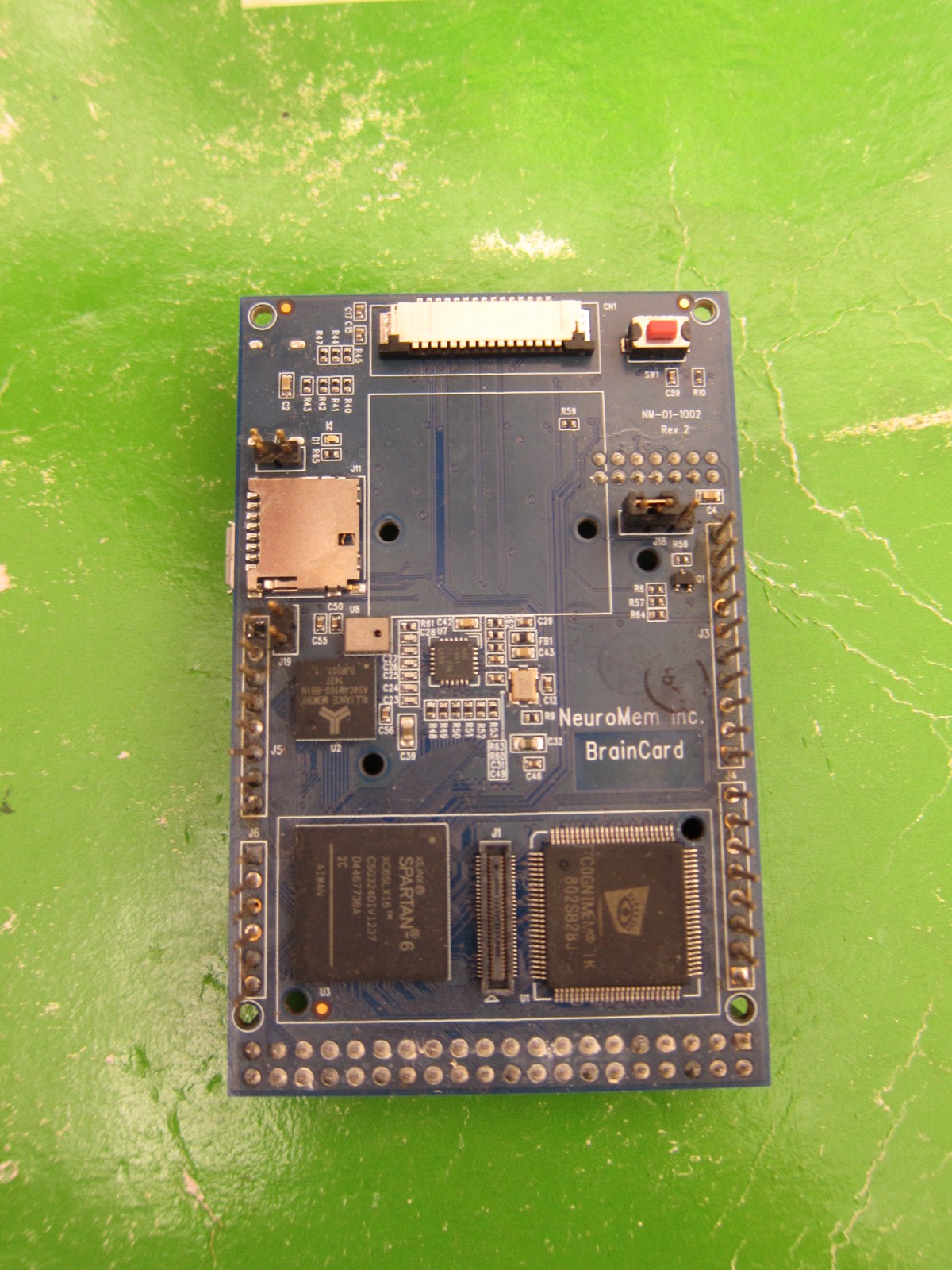


 John Adams
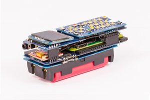
 Arya
Arya
 Michael R Colton
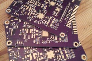
Just a random thought but have you given thought about using multiplexing the analog port? Maybe it is possible to use a few sensors that are modulated and mixed into one signal. You could allow for switching to focus on one sensor at a time through additional hardware or tuning through software to filter each sensor's individual signal. Just a thought around that issue of only having one analog port. It might add bulk, but I'm sure you're skilled enough to make it work.