Close
0%
0%

OpenPnP Automatic Tape Feeder

An Automatic tape feeder for the OpenPnP project with integrated control and system communication.

Similar projects worth following
DIY PnP machines typically utilise the gantry head for advancing component tape. Whilst this is a cheap and simple method it is very slow, easily doubling the time it takes for components to be placed and significantly slowing down small production batches. Because of their simple construction they are unable to utilise many of the feedback and advanced behaviours of their proprietary industrial cousins.

It is therefore proposed to create a universal feeder that provides advanced functionality to the OpenPnP project with the following features:
* Is automated with internal feed motors
* Provides feedback on cycle state, component information and hardware location
* Modular and scalable to fit a variety of tape sizes
* Removable so machines can easily be configured for different production batches.

Accessibility shall be increased for the technology community by utilising easily accessible production technology I.E. laser cut components & 3D printing

System Diagram

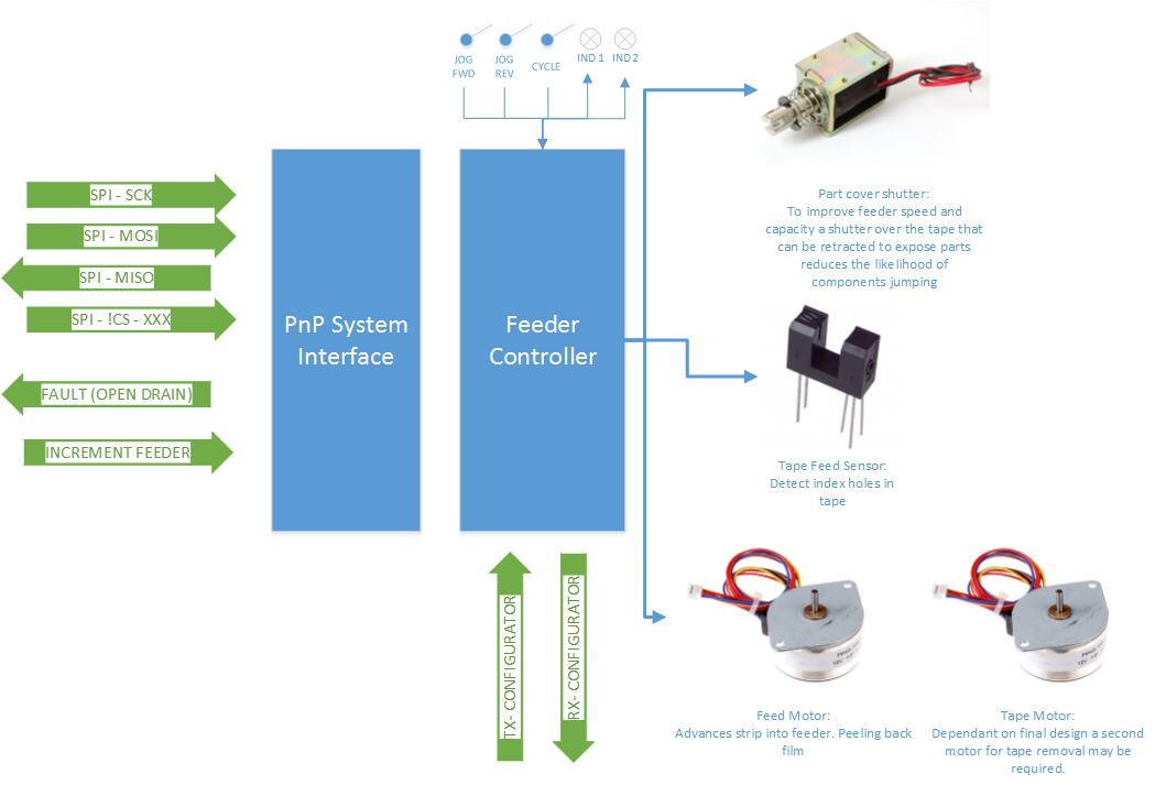
This system diagram highlights the components and communication required for each openPnP feeder.

License

DO WHAT THE FUCK YOU WANT TO PUBLIC LICENSE 
 Version 2, December 2004 

Copyright (C) 2014 Andrew Van Dam


Everyone is permitted to copy and distribute verbatim or modified copies of this license document, and changing it is allowed as long as the name is changed. 

DO WHAT THE FUCK YOU WANT TO PUBLIC LICENSE TERMS AND CONDITIONS FOR COPYING, DISTRIBUTION AND MODIFICATION 0. You just DO WHAT THE FUCK YOU WANT TO.

  • Updated project video

    Andrew 08/21/2014 at 04:08 0 comments

    Finished recording the video for the project entry into the HAD prize.

    Apologies for the poor film quality, my camera does not have an auto-focus. It provides some outline on the project and some of the challenges. It also has some information on a solution.


  • Advancing the tape & additional research

    Andrew 08/19/2014 at 02:49 0 comments

    My original plan was to index the strip forward by pulling the tape off. I have a few manual tape feeders that use this method with some success. In looking for more information on this I came across the eevblog thread about the $300 pnp machine with some interesting discussion on this problem.

    Specifically this video that demonstrates a micro stepper using the tape retraction method!

    In fact it looks as though the system displayed has a lot of potential, clearly indexing the tape accurately and relatively quickly. However it is still limited by the fixed structure of the device with feeders not being removable. So to add a new feeder there is a considerable amount of threading work to be done and it consumes more than a few minutes of machine time. Of course this starts to blur the line between hobbyists and small scale production applications.

    Keeping width down to a minimum is going to be a challenge when it comes to motor selection. A micro stepper like those used in the above example has promise, so long as it can be fitted within the the 15mm pitch of the feeders. The 15mm pitch for the feeders is an important new design specificationand is based uppon the design for the iPulse M7 pnp machine feeder pitch. Some what arbitrary as a decision however it provides a starting point.

  • Manufacturing Methods & Limitations

    Andrew 08/17/2014 at 07:16 0 comments

    As the primary market of this device is for the open source community the components should be easily obtained and structures easily manufactured. 

    Components

    Therefore all components should be sourced from reliable suppliers with tested supply chains, examples being RScomponents, Mouser, DigiKey, Element14,  Sparkfun, Adafruit etc. This will increase the cost of the system vs using chinese suppliers such as aliexpress however they are accessible to more people and typically more reliable.

    Manufacturing

    Most hobbyists now have reliable access to a variety of manufacturing tools.  

    3D Printers. Through services such as PonokoShapeways3D printing studio.  As well as personal extrusion machines at home and maker spaces around the world. Components printed can be course and take significant fine tuning to ensure accuracy. I am hesitant to use them for high accuracy requirements.

    CO2 laser cutter. Less common at home although a staple of hackerspaces. Considerably higher accuracy although they are limited to cutting wood and plastics. Wood components are likely to warp and are also prone to flutuations in temperature and humidity. Plastics are good for components that are subject to wear and need to provide a level of slip. 

    Industrial laser cutter. Unavailable as home machines or hacker spaces however they are still easily accessible with laser cutting suppliers in most major citys around the world with cheaper minimum orders available through the years. High tolerance machines that are capable of cutting multiple steel alloys and grades. 

    CNC mill & lathe. Harder access to machines, available only to the most equipped hackerspaces and home workshops. Very high tolerance components can be machined in a variety of matterials. Unlike industrial laser cutters commercial machine shops are less likely to do small order runs and therefore the cost of manufacture can be very high.

    Material Options

    For the easiest mounting and most reliable fit a combination of industrial laser cutting and 3D printing will be used. In this way some users can substitute the metal components for wood or plastics however the design will allow for a higher tolerance fit.

    Back mounting frame: Sheet metal

    Feeder guidance: 3D printed channel

    Feed cover: sheet metal

    Take up reels: 3d Printed plastics

    All 3D printed parts will come will be designed so they can be manufactured from billet steel in the event someone has access to a mill for fabrication.

  • License and System Diagram

    Andrew 08/17/2014 at 05:38 0 comments

    Just a quick update today on license of the work and the system diagram.

    In actually stopping to look at the license for this project as opposed to slapping on the common GPL Vx license I found one the mirrors many of my sentiments about licensing. the every classy, ever tasteful, not at all unprofessional

    DO WHAT THE FUCK YOU WANT PUBLIC LICENSE

    As i stated, it is a classy affair. In reality the license is essentially identical to releasing the work into the public domain. However with a little extra flourish and political sentimentality. The wiki is here, as well as some interesting discussion on the professionalism and challenges of using the DWTFYW.

    System Diagram

    This project does not take a lot of rocket science to work out. The system is relatively simple with communication to a host system (the PnP machine) and a few outputs to motors and sensors for the closed loop control. 

    SPI Bus

    An SPI bus provides simple communication from the host to all feeders. This allows the communication of additional information such as fault conditions, remaining components, feed rates, component pitch, low part count warmings etc. SPI is a simple protocol that most devices can interface with and reduces wiring complexity from the host.

    IO signals

    To improve functionality and allow for a reduced complexity system an input and output are provided. The input is an incremental part feed signal triggered on the rising edge. The output is an open collector drain signal for fault indication, such as a mis-feed, jam, empty feeder etc.

    Hardware

    Several motors and potentially a solenoid are going to be required in this system. Closed loop feedback is achieved with a photo interrupter over the holes in the tape. This ensures no mis-feeds occur in the system and can detect jams.

    In a further update further options for the control system will be analysed.

  • Research

    Andrew 08/07/2014 at 03:47 0 comments

    Over the past week or so I have been doing a lot of background research and exploring some of the existing solutions.

    This project has the advantage of working from existing commercial solutions. No point re-inventing the wheel or sprocket feeder in this case...

    Commercial Units:
    Mechanical - Some older units utilise a series of mechanical linkages to increment the tape when a bar above the unit is actuated from the picking head.
    Electrical - Modern units make use of cheaper electronics to advance the tape with electric motors. Styles vary drastically, all of them spool the cover strip in some manner then let the empty tape dump onto the floor. Electronics allow for smarter systems with feedback to the controller and additional information.
    Drag - Very cheap machines like the TM220A utilise the picking nozzle to advance the tape.

    Mechanical Systems:
    Advantages - Simple, fewer parts to fail, long life span with metal construction
    Disadvantages - Complex to design, high tolerances required for manufacture, no feedback, fiddly to 

    Electrical System:
    Advantages - Significant system feedback on feeder state, Chip counting, easily adapts to different components
    Disadvantages - Mechanical and electrical design required, reliable common sources of compact motors difficult

    Existing DIY designs

    There are very few examples of open soruce designs. Most people with advanced openPNP projects are using commercial feeders found on eBay or similar. This is the only example I was able to find of existing works http://tim.cexx.org/?p=803

    There are existing threads on diy PNP systems http://www.eevblog.com/forum/chat/better-pick-and-place-machine-diy/ This thread specifically makes mention of feeders being the most critical component of an open PNP system.

    Vibrating chip feeders have also been developed however they have none of the design challengs that a tape dispensor has. http://www.briandorey.com/post/DIY-Pick-and-Place-V2-Vibratory-Chip-Feeder.aspx

View all 5 project logs

Enjoy this project?

Share

Discussions

Capt. Flatus O'Flaherty ☠ wrote 04/12/2017 at 08:50 point

I like your licence agreement and the fact that hackaday allows some of the more esoteric anglo-saxon words!

  Are you sure? yes | no

K.C. Lee wrote 07/27/2014 at 10:54 point
Not my area, but this is what I think.

I like your idea as the pick & place takes away the limited work area available (especially in converted 3D printer) for populating the PCB. I think of it like the surgeon's assistants hand him/her the tools/materials requested so the he/she doesn't need to move away from the patient in the OR.

The feed system also do not require the same level of degrees of freedom/resolution as the pick & place heads as the reels or individual loose tapes are quite wide. Also multiple of such units can be use to get part in parallel.

  Are you sure? yes | no

Andrew wrote 07/27/2014 at 12:21 point
Thanks K.C.Lee i think it will be a great next step for home brew electronics and small scale manufacture.

The precision does not need to be too high, especially with machines that use flying vision, they can locate the components provided they are within an aproximate area so your cost of motor control and complexity of code is reduced.

It is not unusual for some machines to have upwards of 50 units, even for small manufacturers. Unfortunately a lot of commercial feeder units can cost upwards of $300 each.

  Are you sure? yes | no

Similar Projects

Does this project spark your interest?

Become a member to follow this project and never miss any updates