 deʃhipu
When I started planning this board, I only knew the HT16K33 LED driver chip (well, ok, also the MAX 7129, but that's ancient). That chip has a pretty cool feature -- by adding a diodes to the column pins you can re-use them to scan a matrix keypad at the same time as they drive the LED matrix. The chip even does de-bouncing for you, you just have to read the state of the keys from its registers. Super-convenient for a device like this.
Unfortunately, the IS31FL3733 chip that I'm using now, while it allows me to control the brightness of each individual pixel, doesn't have such a keyboard-scanning feature. But wait, the datasheet mentions something similar -- it has an open/short LED detection. Isn't a closed button pretty much electrically equivalent to a shorted LED? I could use this, together with the extra column pins that I don't use (the chip supports 12x16 matrixes, I only have 8x16) to scan the buttons!
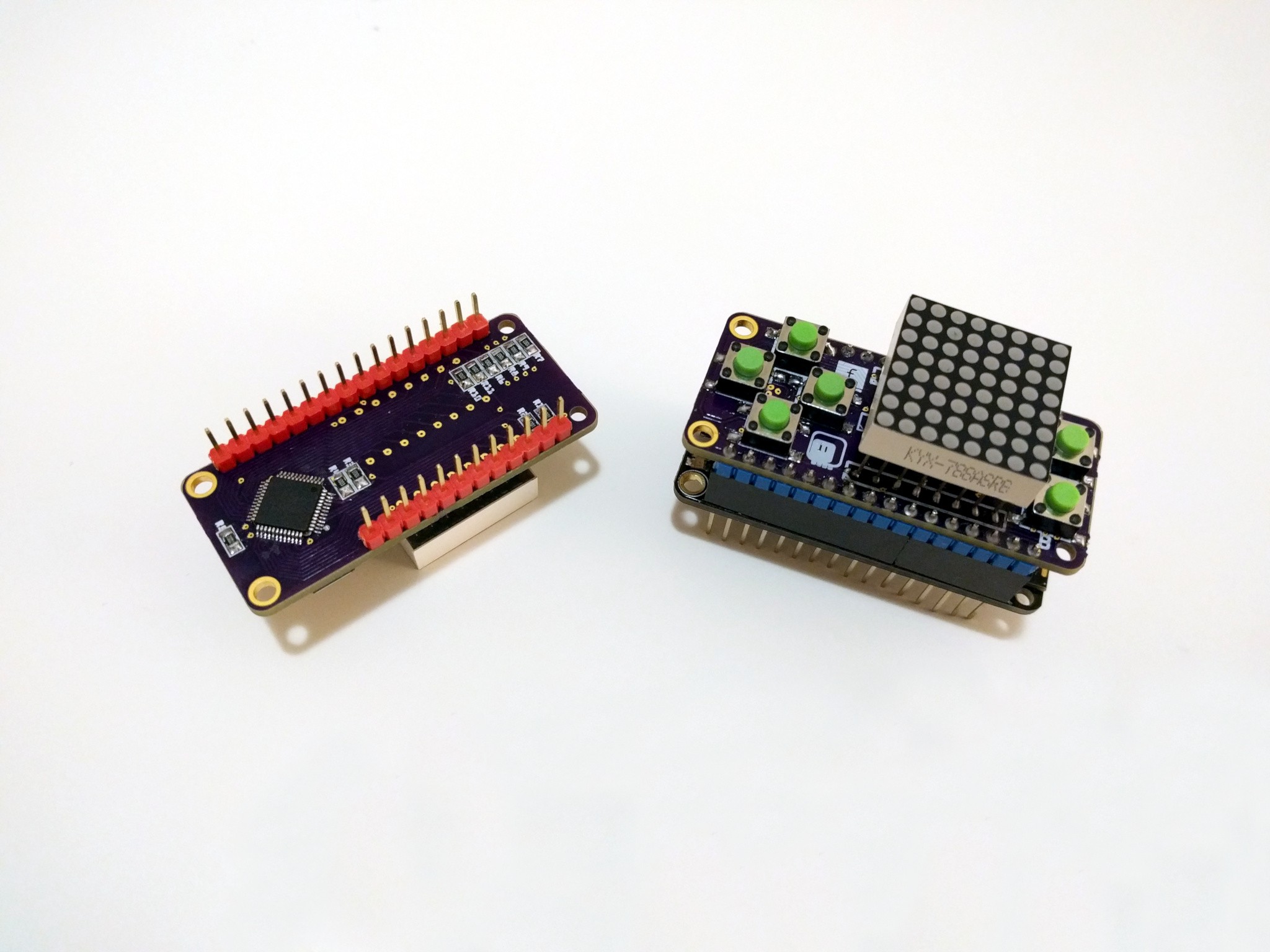
I designed the first prototype with that idea in mind. The buttons are connected -- through resistors, for safety -- in place of LEDs on an extra column. Once the PCB arrived and I assembled it, I could start my tests.
Turns out getting this mechanism to work properly is a little bit involved. First, the LEDs need to be enabled by writing 1s to the corresponding registers on the page 0. Then, the power register on page 3 needs to be set to 1, the minimum power setting. I experimentally determined that this step is not actually strictly necessary for the mechanism to work, but it's probably there for safety, and it prevents the LED matrix from flashing brightly while the chip tests all the lines. Finally, you have to trigger the testing by writing 1 to a bit field in the config register on page 3. Then you have to wait 3.264ms, and finally you can set the current back to what it was, clear the bit field in the config register, and read the LED status from the registers on page 0. Easy.
I got my code to work, and decided to try and write a simple snake game to see how well it all works. Turns own that it works pretty bad.
You see, to get a decent responsiveness from the buttons, I need to scan them often. At the minimum once per the game's animation frame. Humans are very sensitive in delays in tactile and visual areas -- especially tactile. So I need to scan often. But you see, to scan I need to drop the current to the minimum setting, which effectively switches the display off. And if I do it for 3.265ms every frame, I get a nasty flickering. The board also makes some suspicious high-pitched noises, which can't be good.
So that's it for the first prototype. I need to find a better way of handling the buttons. That prototype was going to be trashed anyways, because I made the holes for the matrix pins too small -- that's why the matrix is soldered on top, and not flush with the board on the photos.
Discussions
Become a Hackaday.io Member
Create an account to leave a comment. Already have an account? Log In.
That's a smart hack ! Next time it will work :-)
Are you sure? yes | no
Thanks. I guess I will keep it in mind for something that only needs to check the buttons once in a while (or only needs to display something *after* a button has been pressed).
Are you sure? yes | no