 deʃhipu
I decided to assemble one of the "production" boards I made — that is, solder the pin headers and the matrix and plug it into a feather. Sure enough, there are problems. The left button doesn't work, and one of the columns doesn't have the red color.
So I started debugging.
The button problem turned out to be due to a broken trace on the board — they claim they do continuity testing at Seeed, but apparently this one somehow slipped through. Adding a wire solved that.
The column must be a short somewhere, because adding wires doesn't help. I suspect it's a short with a via under one of the buttons. I will try to remove the buttons tomorrow, and see.
But that made me realize that I really have to test the assembled boards somehow before I send them. The hot air soldering is very fast and convenient, but it's not as reliable as doing it with a soldering iron, and sometimes I have to touch it up a bit afterwards.
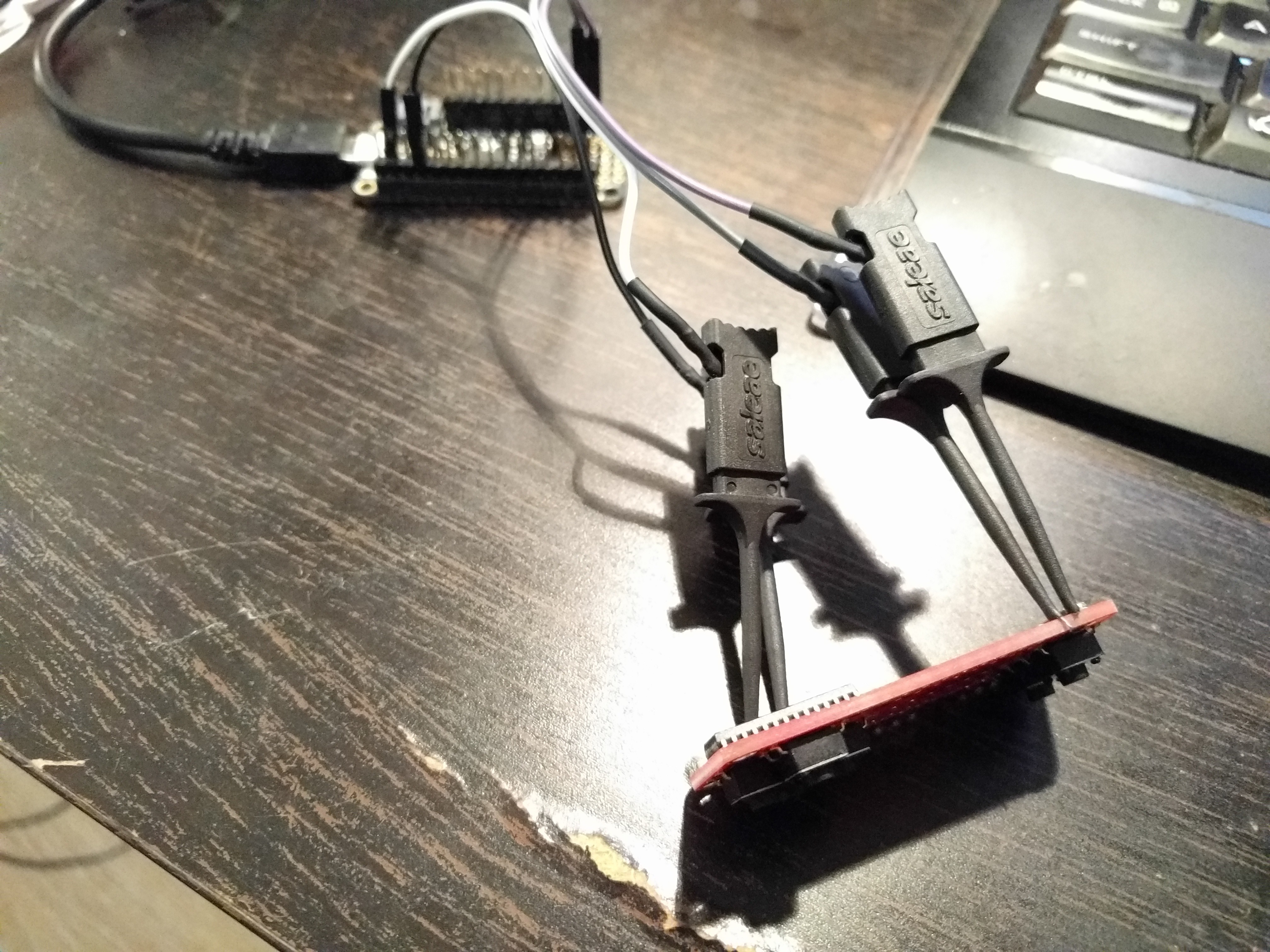
There isn't really much I can do with the matrices without soldering them (and I can't solder them before the headers are soldered, and I can't solder the headers because that would make the whole thing hard to ship), but I have already tested them separately, and there is very little chance of a problem with those connections. But I can at least test that the chip is properly powered, that the I²C communication works, and that all the buttons work. So I made a small testing jig for this:
Out of 8 boards that I have soldered so far, one had a broken trace, two had a cold joint that had to be touched up with a hand soldering iron, and one had a short between two of the buttons (the new buttons have a bit wider legs and barely fit in their space). Except for the first one, all of them were easily fixed.
I'm still thinking about some way of possibly testing the matrix connections — maybe I will build something with pogo pins.
Discussions
Become a Hackaday.io Member
Create an account to leave a comment. Already have an account? Log In.
IMO pogo pins are the way to go. Just order a batch of 100 from DirtyPCBs, they have quite an assortment of all kinds of pogo pins, and a description of when to use which ones =) http://dangerousprototypes.com/store/designer/details/ian/12/dirty-pogo-pins
Then, open your gerbers in gerbv, select outline and drill layers, export in SVG, remove vias in Inkscape and send to a laser cutter, iterate with hole diameters until pogo pins fit just right and you have a testing jig. Then, add some kind of fastening mechanism, since pogo pins push the board away - I see you have holes in your board, 4 of them, which is just great. https://hackaday.io/project/19035-zerophone-a-raspberry-pi-smartphone/log/53016-hardware-alpha-board-testing-jig
Are you sure? yes | no
I found an easy way to test the matrix without soldering:
Basically, I use the long stacking headers, bent to provide good friction. It was good enough to let me see that each of my boards had this problem with the leftmost column not displaying red. I started debugging them, disassembled one almost completely, and then realized that the problem is in software...
Are you sure? yes | no
you could maybe make the diameter of the LED matrix wholes smaller, do you don't have to bend the headers too much.
Are you sure? yes | no
No, if anything, I would rather make them larger. I had them smaller in the early prototypes, and inserting the matrix into them was a challenge. Especially since if I want to ship the boards without the headers soldered (and I do, because then it's cheaper and you can use any headers you like), I also have to let the users solder the matrix, since once that is on, you can't access the headers.
Are you sure? yes | no