 Langhalsdino
With Funky Light we describe two different Layers, one of them is the server side and the other one is the client side. We want to design the server side independent from the client, so we could easily exchange the client for an off the shelf product (DIY didn’t work all the time in a school environment especially when the developers left the school).
The Server Side is quiet complex and should be the hub between the physical world (Lights) and the client, but with the addition that the server uses a common used communication protocol to talk to the client. In our case we choose OSC (Open Sound Protocol), because it is commonly used to control mixing tables. To build our server we used an Arduino Yun with a custom made Shield, you find more details in the Server section below.
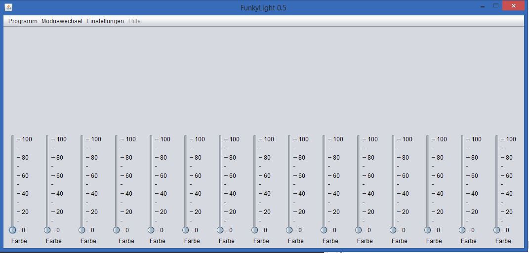
Besides the fact that you could use Funky Light with any Software that is capable of using the OSC protocol we start designing our own software that is specially build for this case. So we have an easy to use bundle that consists of the server as well as a client. We wrote a detailed description in the Client section below.
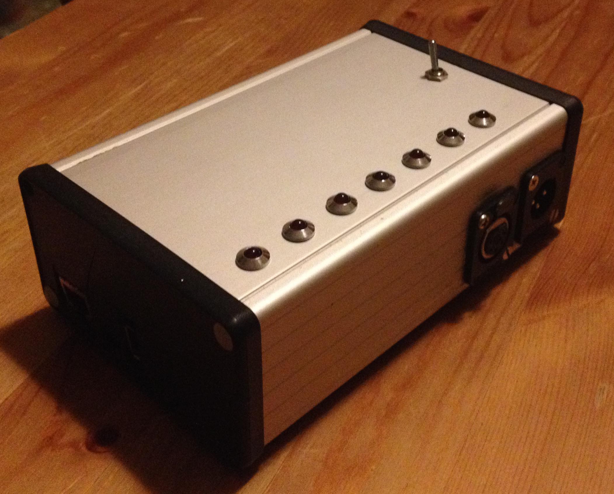
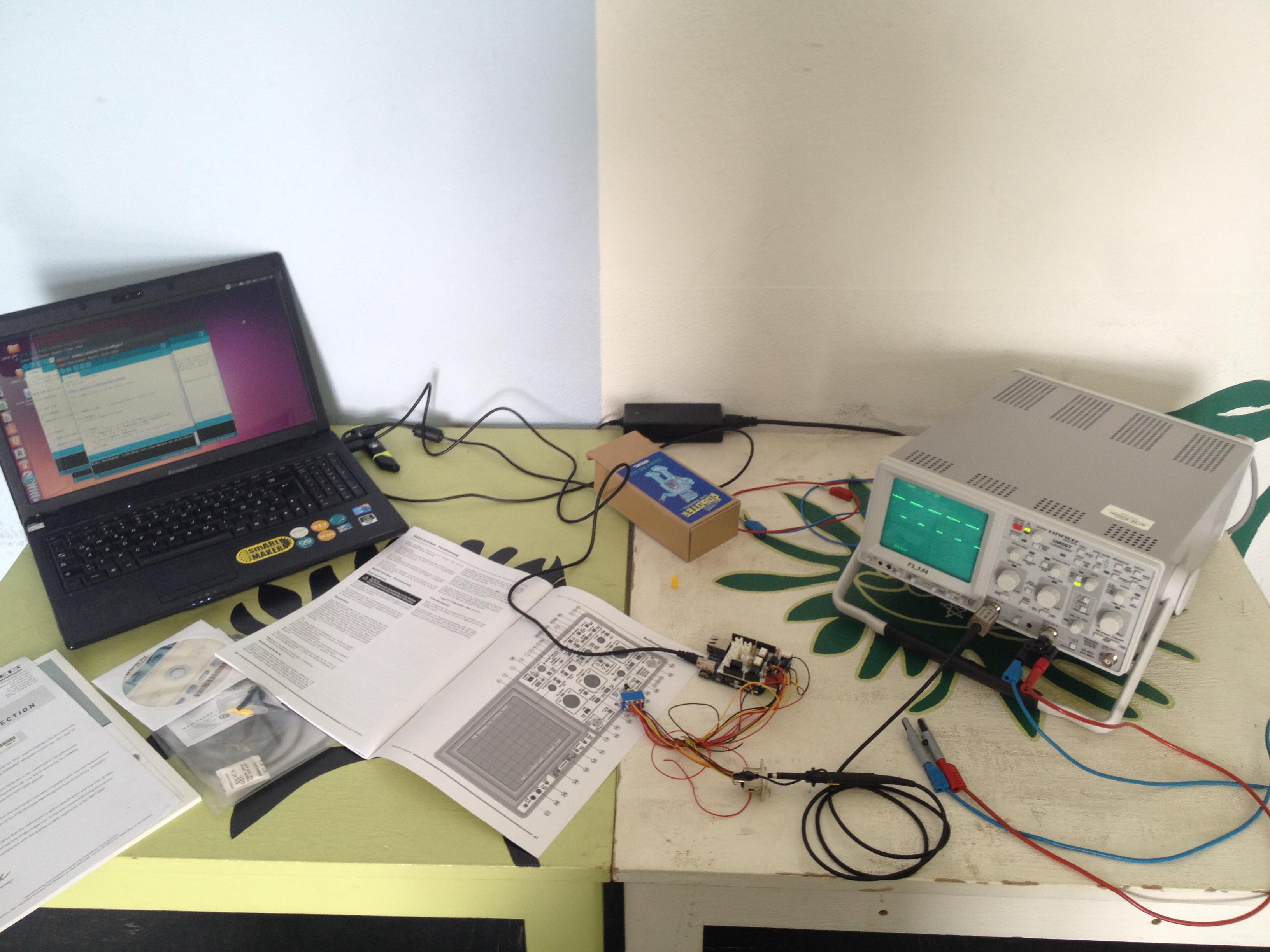
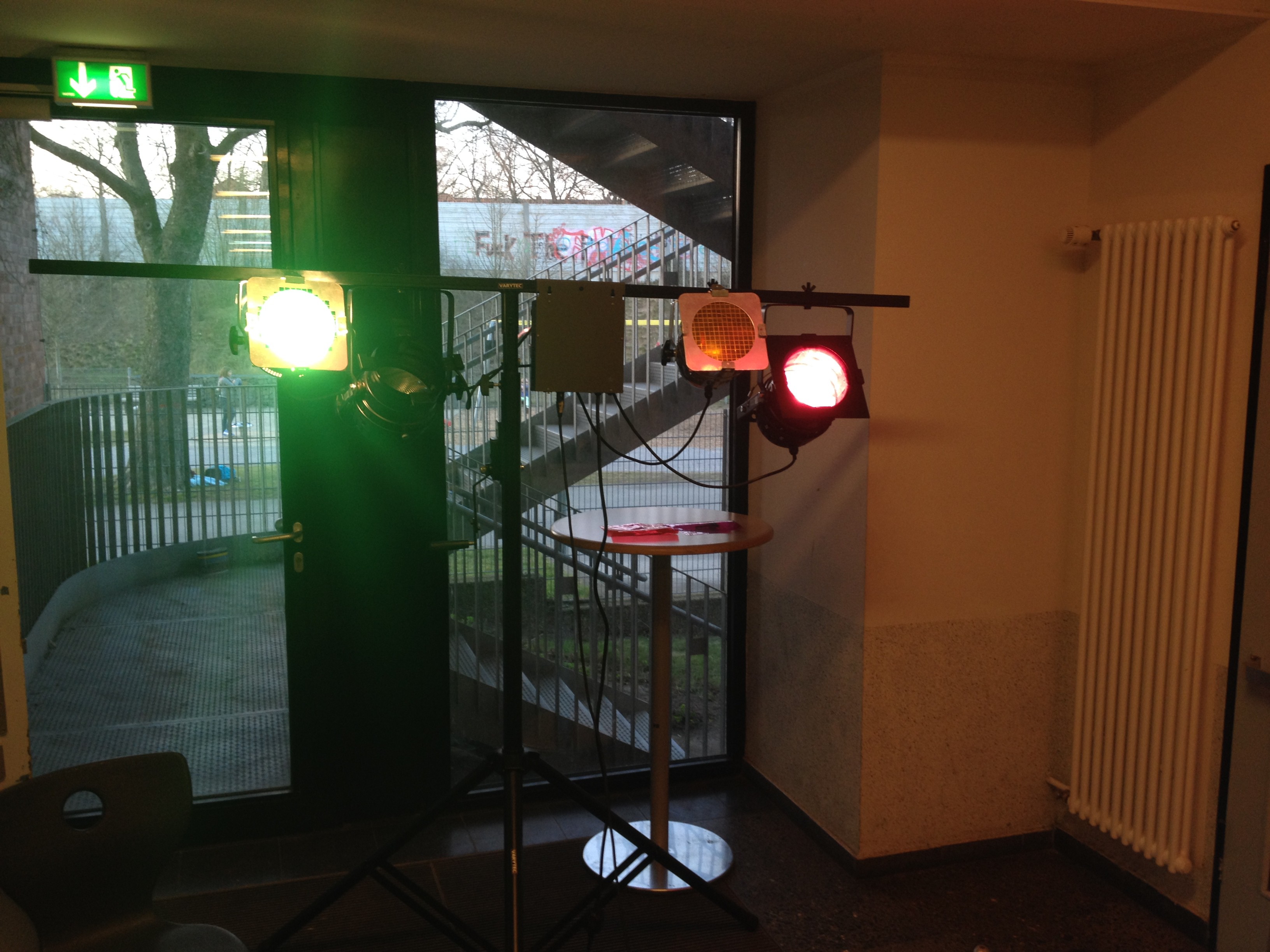
We already managed to build a prototype and tested it in the assembly hall of our school. We would love to get your opinion on our project so we can improve Funky Light.
The Server Side of Funky Light
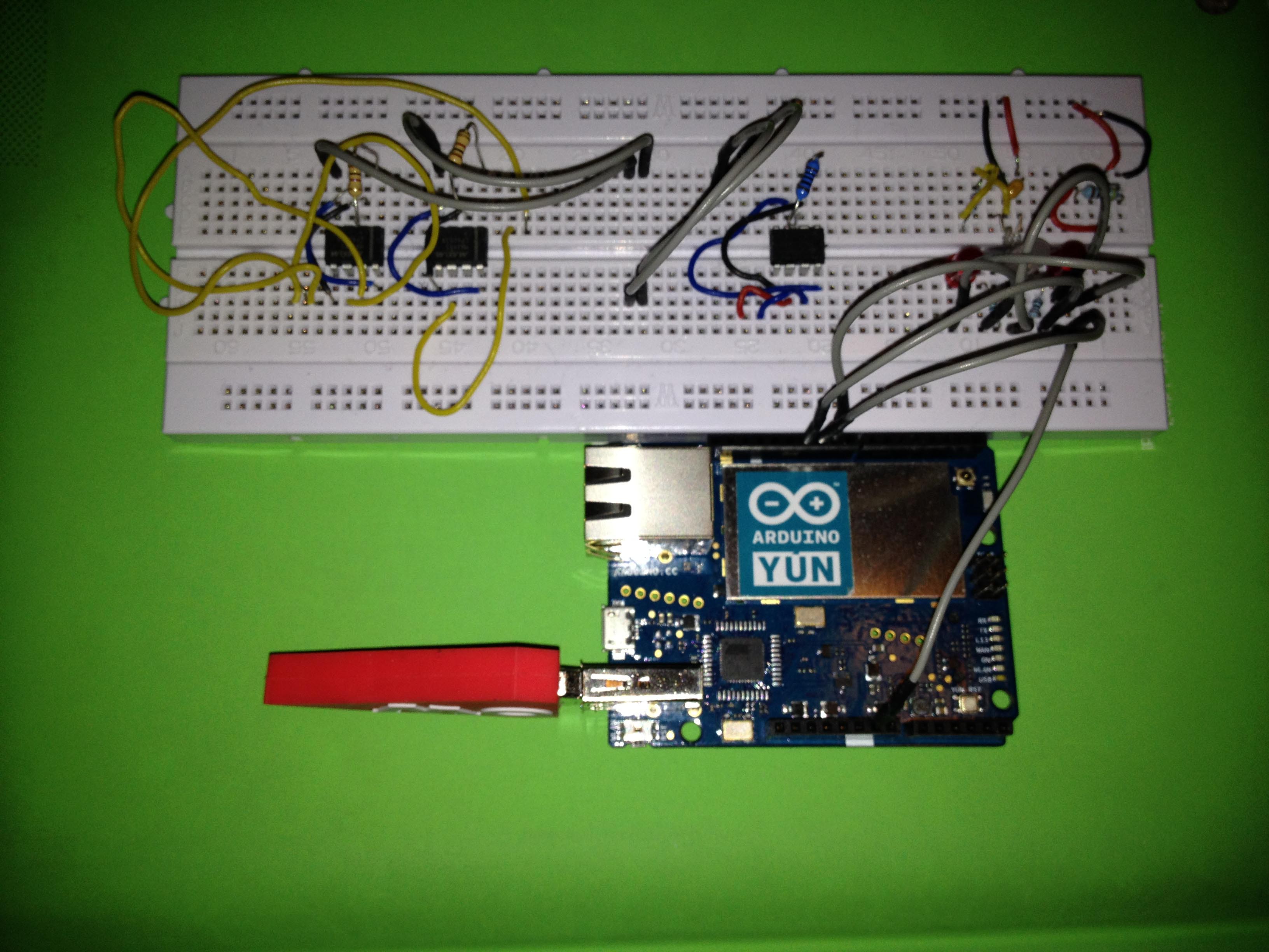
Okay let’s talk about the server side, first of all I want to give a short overview. The Hardware of Funky Light is based on an Arduino Yun with a custom made PCB that controls 3 DMX universes. Two of them are outputs and the third universe is used as an input form mixing consoles or whatever.
Before we describe the actual design of our hardware we want you to know why we use this type of setup, if you are not interested you can skip that part and continue reading in the Hardware section.
One of the first question that we had in mind was, how the client talks to the server. After a lot of research we decided for OSC, because it is a commonly used protocol in similar projects. And since every teacher and student should be able to control the whole system with their own device, we needed the server to support ethernet as well as wifi. At this point we started searching for a the right development hardware that supports wifi as well as ethernet in association to a microcontroller that should handle all the DMX stuff. The cheapest and easiest Hardware we found was the Arduino Yun, so we continued working with the Arduino Yun.
So why to outputs and one input universes, the main reason why we used to output universes isn’t that we actual need it, we will never have enough lights that need all the two times 512 channels. Moreover it is the fact, that most schools use the 5 pin DMX cables, which are capable of two DMX channels, so they can easily distinguish between audio cables and data cables. So why not supporting two output universes.
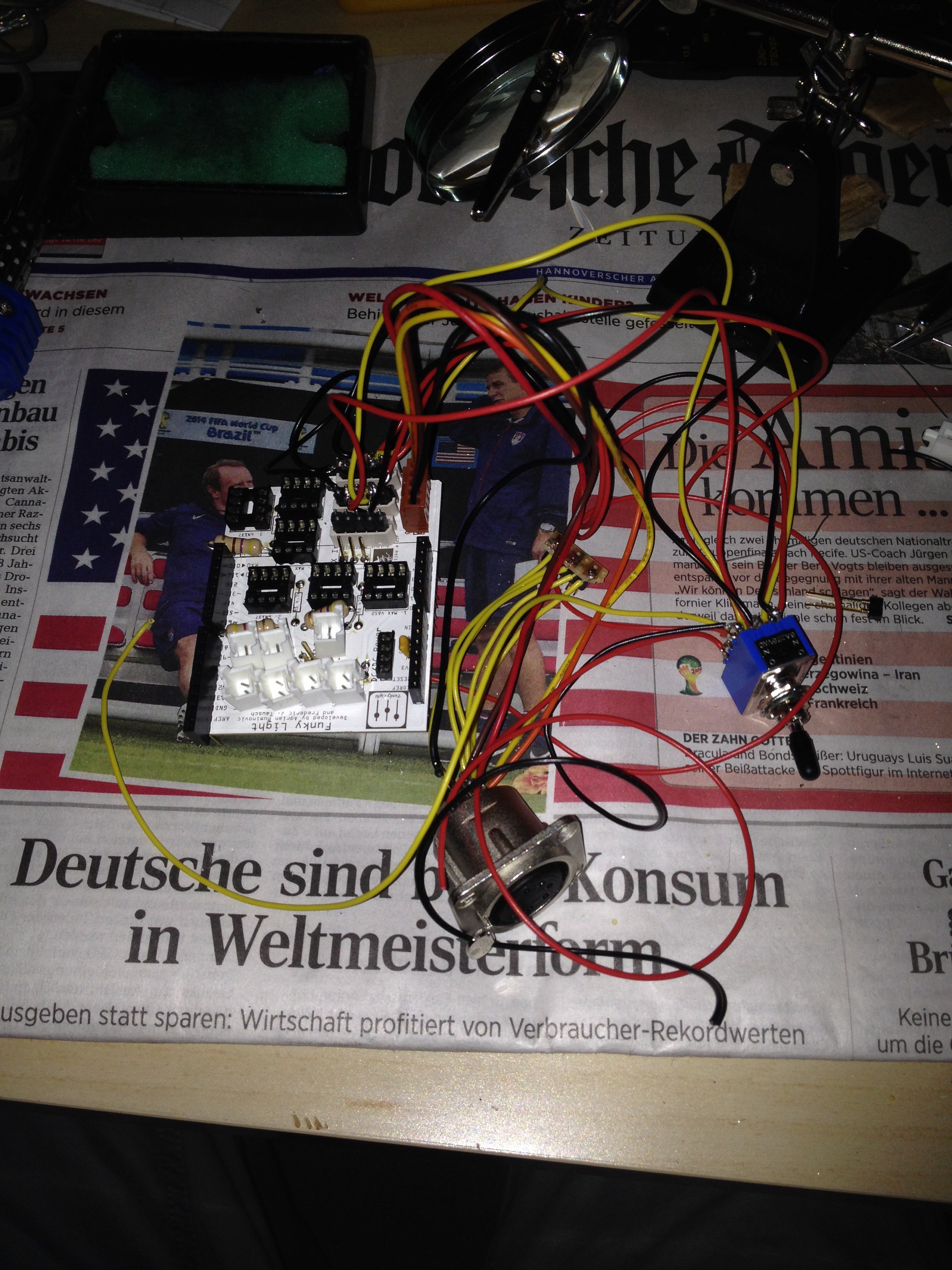
Additionally we build in a safety feature, because complex hardware and software always fails when it matters. The safety feature is a switch that defines the source of the output signal, you could choose between the generated signal from the Arduino and the signal from the input universe, so we can ensure that the lighting control never fails.
The Hardware
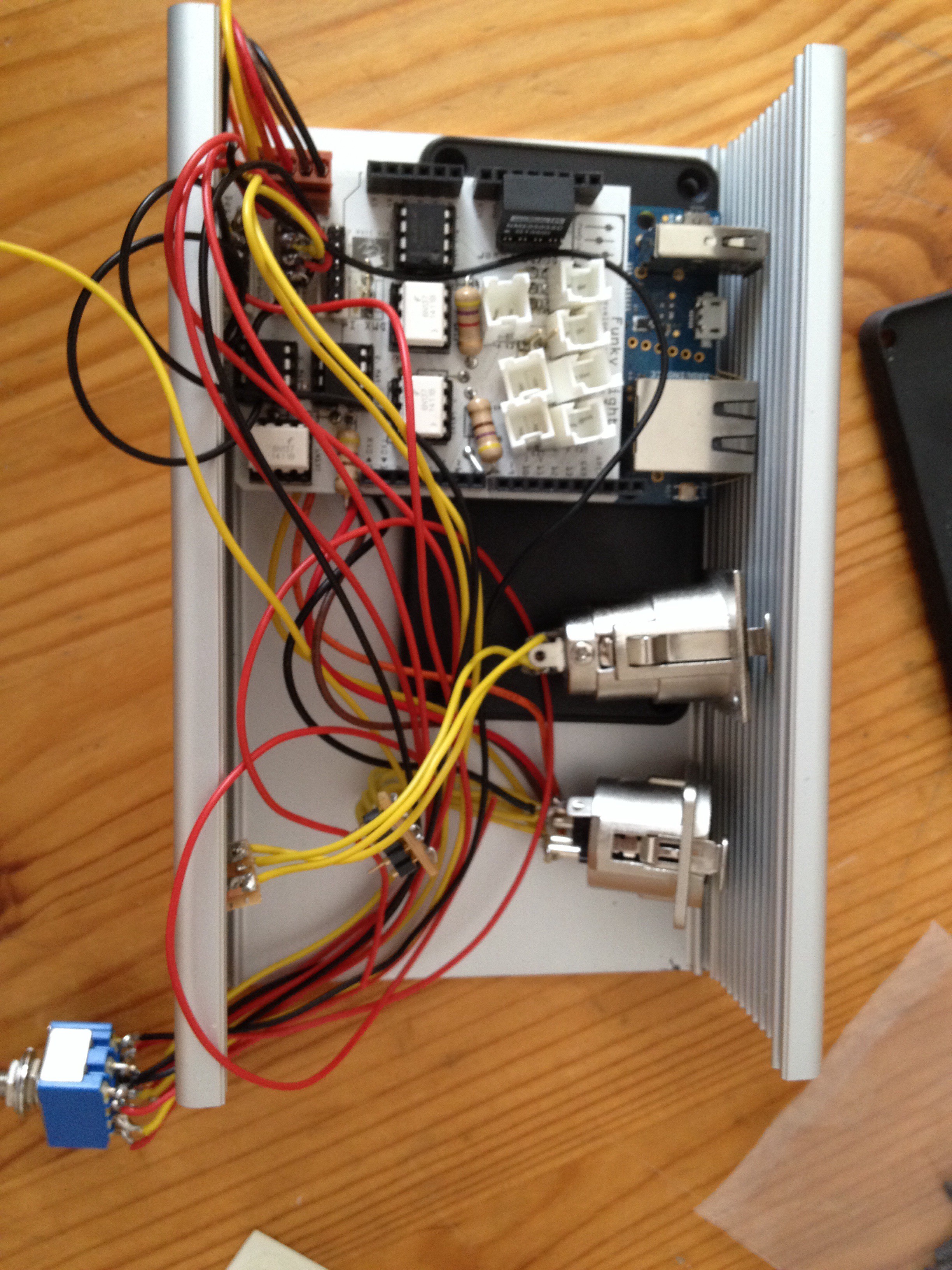
Okay let’s start digging deep into the Hardware, especially the Arduino shield.
The Hardware of the server side consist of several parts:
- A Linux operating system that runs some python scripts to manage all the clients and bumping messages around. For that we used the Linino of the Arduino Yun.
- A Microcontroller manages the he whole DMX data output, for that we use the microcontroller of the Arduino Yun.
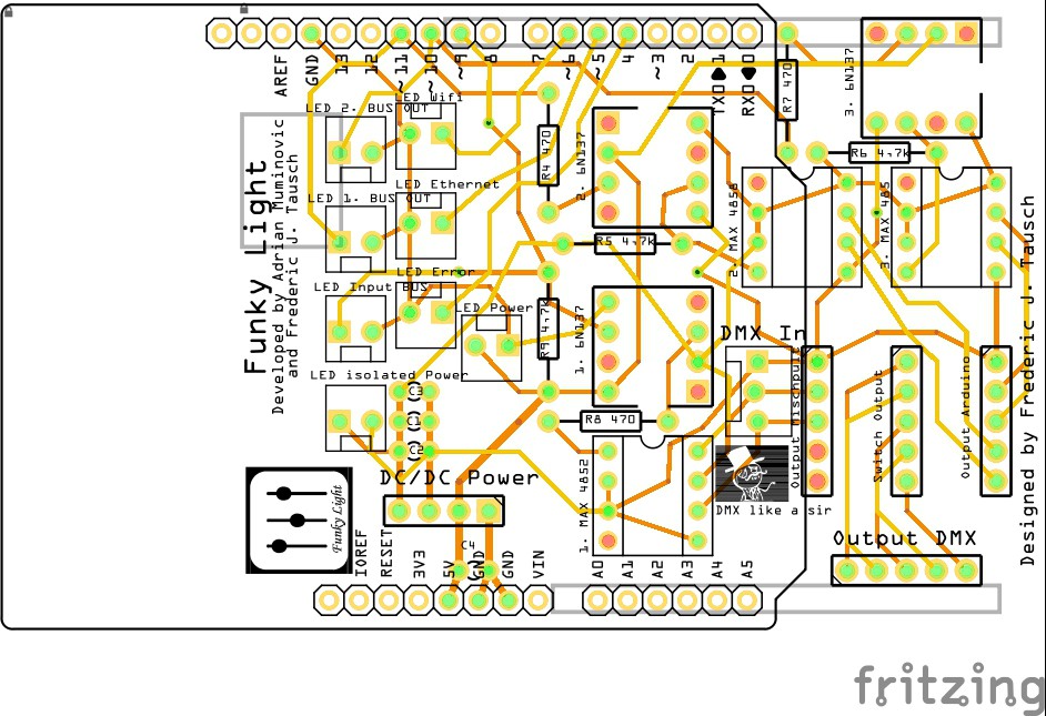
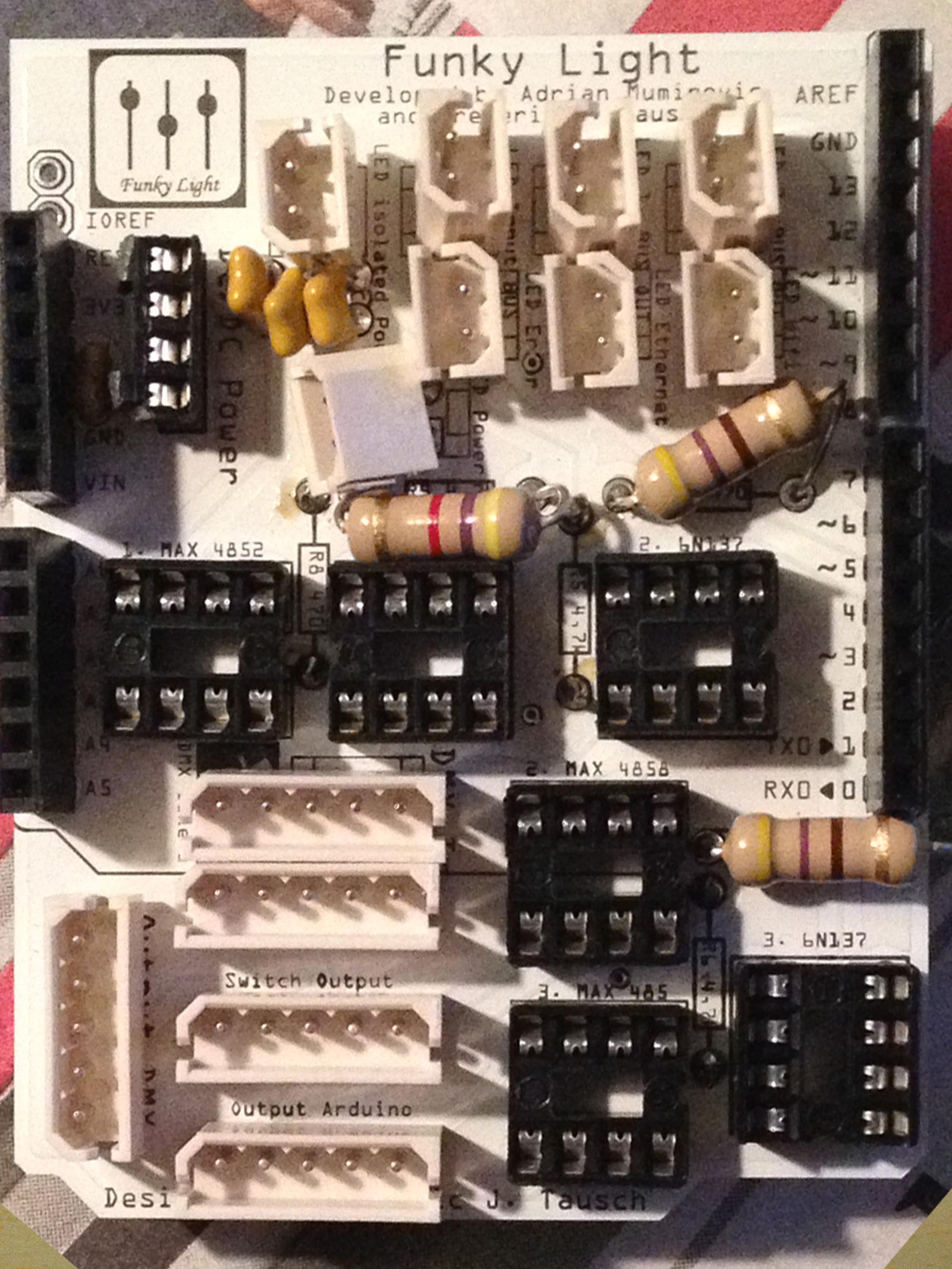
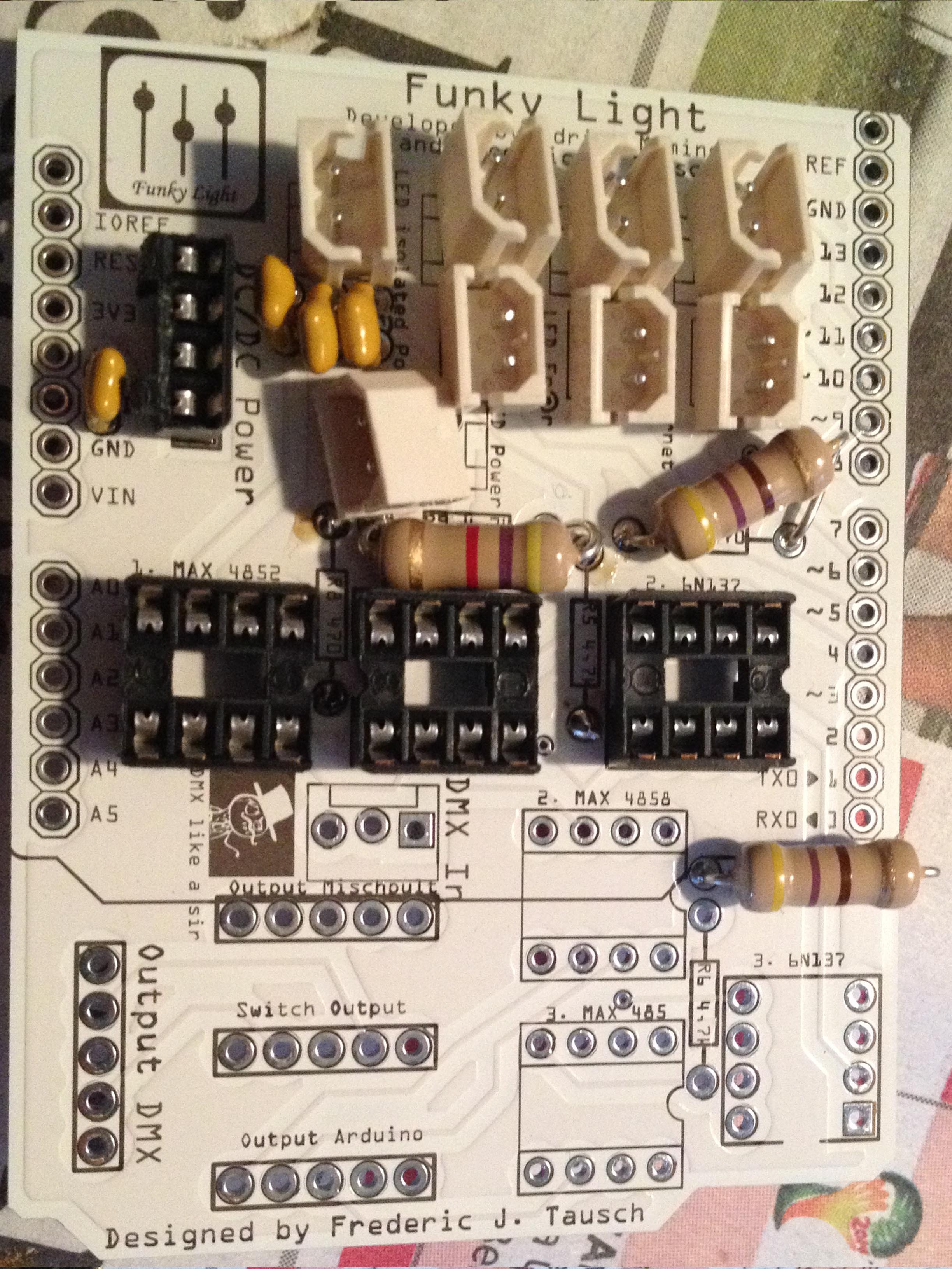
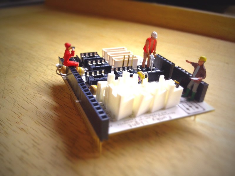
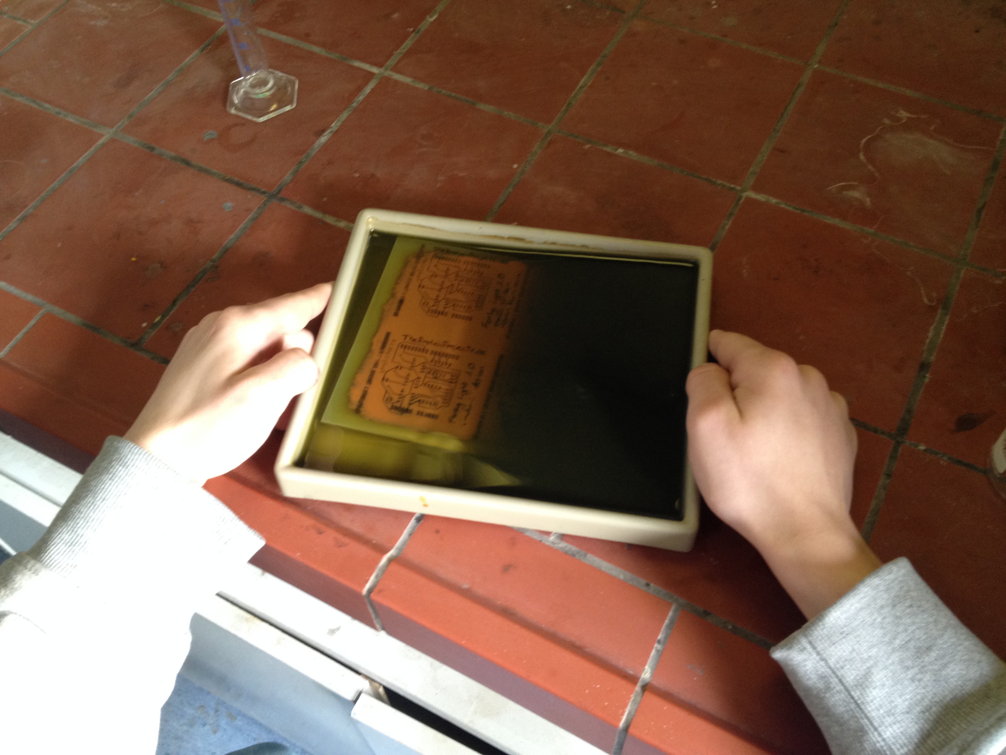
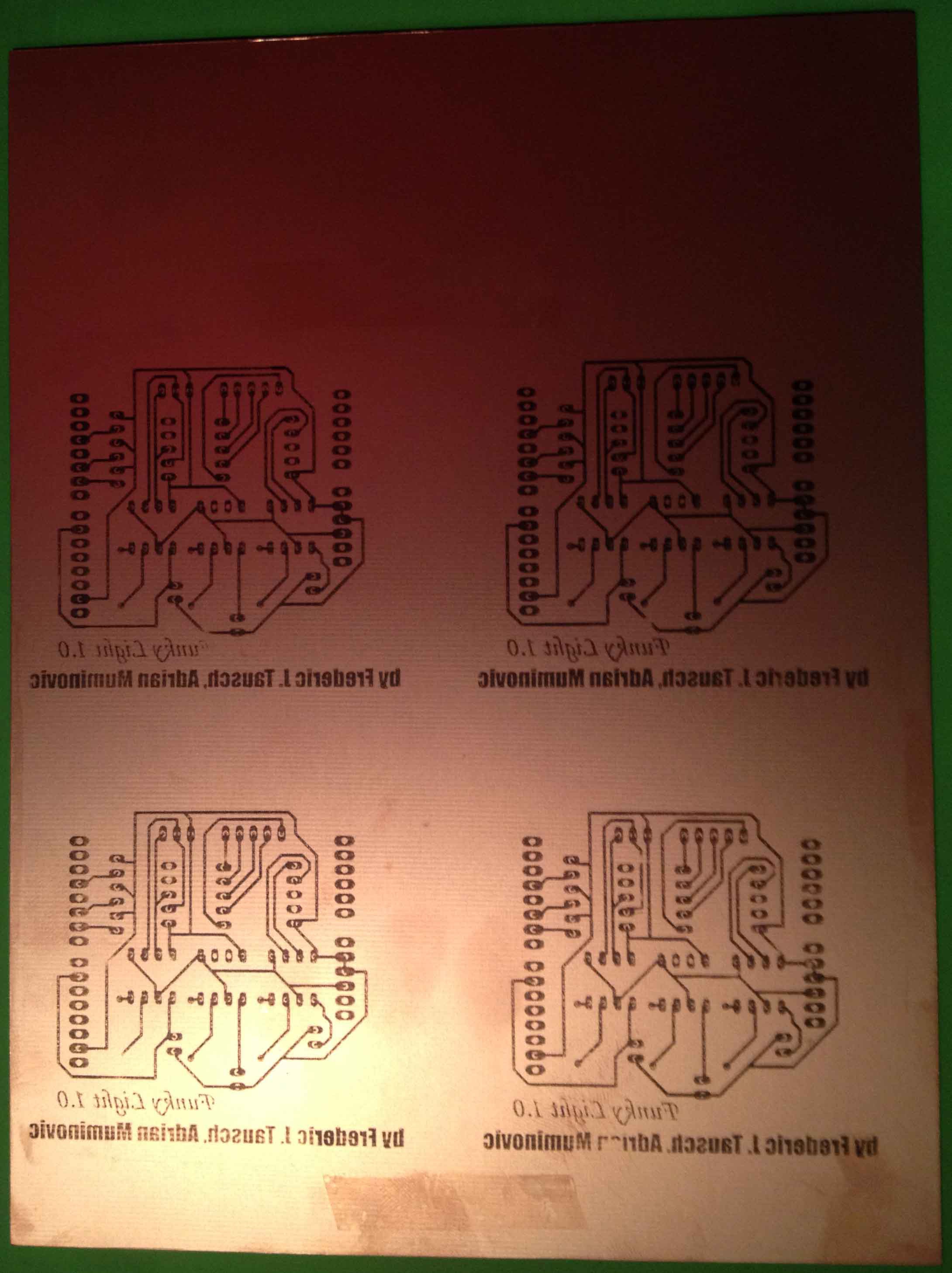
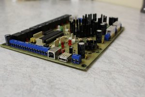
- A custom Arduino shield separates the circuit of the Arduino Yun from the DMX signals with some Optocouplers. Additional it does all the additional work to get from a Single Bus to the DMX pinout. The schematicsfile are here (The Geber Files).

You could find a detailed overview of the whole structure in the nice diagram at the end of the detailed description.
The...
Read more »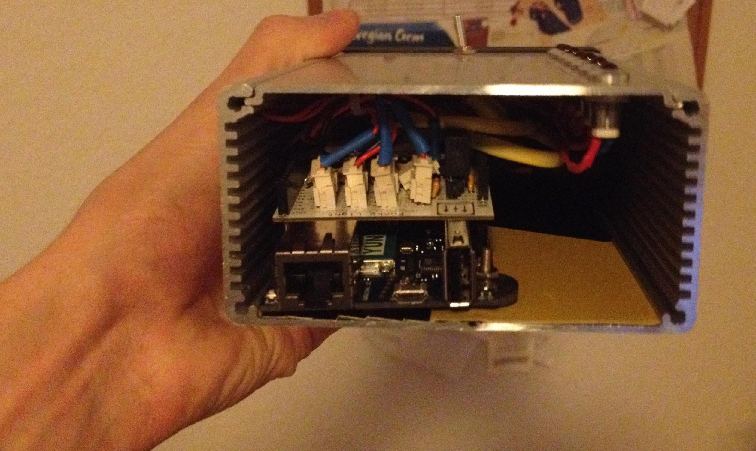

 Dewet
Dewet
 Keenan Pinto
 Anderson Antunes
 drewrisinger